Mine tray for prejudging magnitude of anchoring force on basis of surface deformation and monitoring method

A technology of surface deformation and anchoring force, applied in mining equipment, mining equipment, earth-moving drilling, etc., can solve the problems of bolt breaking and popping out, nut falling out and ejection, unrealistic and other problems, achieving good popularization and demonstration. The effect of high stability, obvious technical benefits, and simple and convenient process

Inactive Publication Date: 2020-03-24
CHINA UNIV OF MINING & TECH
View PDF7 Cites 3 Cited by
  • Summary
  • Abstract
  • Description
  • Claims
  • Application Information

AI Technical Summary

Problems solved by technology

Considering practical factors such as economic cost, time-consuming installation, and time-consuming data collection, it is unrealistic to install pressure gauges for each bolt support system to monitor its anchoring force. However, traditional technical solutions have many monitoring blind spots. , poor data contrast, data collection is greatly affected by coal dust and other negative factors. At the same time, the pressure gauge also has a certain failure rate in practical applications, which cannot truly reflect the real force of the bolt body
In the background of this engineering technology, in coal mines, accidents often occur in coal mines where the nut comes out of the bolt without warning or the bolt breaks and pops up to injure people, or a small area of ​​deformation and collapse accidents occur, resulting in the failure of the bolt support system to be effectively integrated with other systems. Support system produces synergistic effect

Method used


Image

  • Mine tray for prejudging magnitude of anchoring force on basis of surface deformation and monitoring method
  • Mine tray for prejudging magnitude of anchoring force on basis of surface deformation and monitoring method
  • Mine tray for prejudging magnitude of anchoring force on basis of surface deformation and monitoring method

Examples


Embodiment Construction

[0041] The present invention will be further described below in conjunction with accompanying drawing.

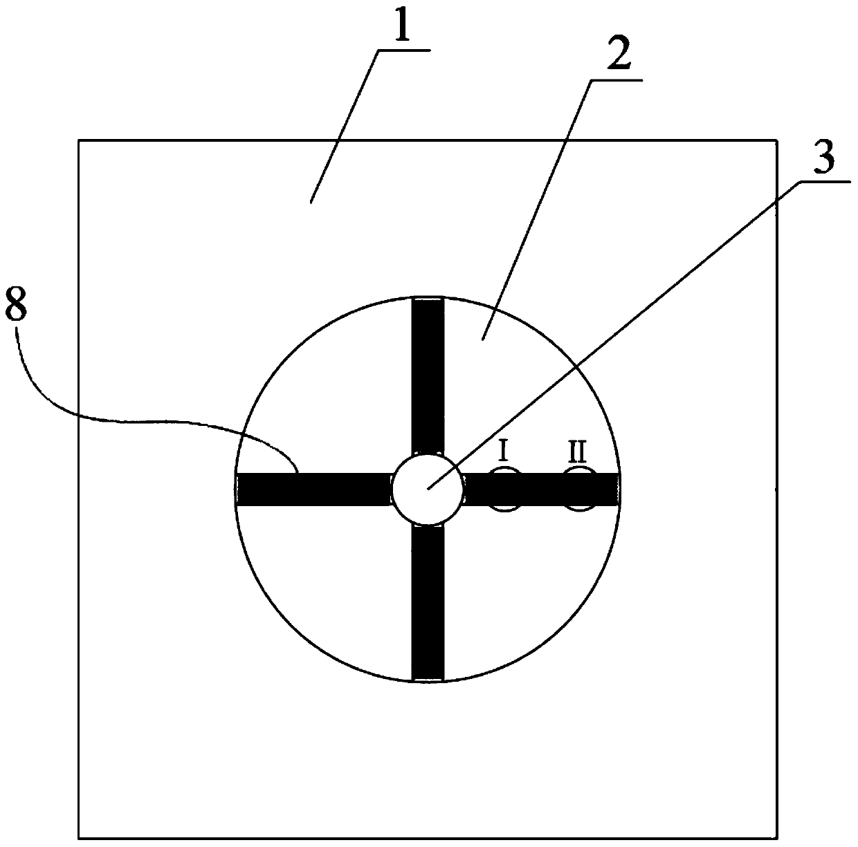
[0042] Such as Figure 1 to Figure 15 As shown, a mine pallet that predicts the anchoring force based on surface deformation includes a pallet body and a deformation identification unit; the pallet body includes a spherical crown-shaped part 2 in the middle and a flat part 1;

[0043] The deformation identification unit includes four strip-shaped plastic sheets 8, and the four strip-shaped plastic sheets 8 are adhered to the surface of the spherical crown part 2 in the shape of a cross, and one end of each strip-shaped plastic sheet 8 starts from the anchor rod hole 3 edge, and the other end extends to the edge of the spherical part 2;

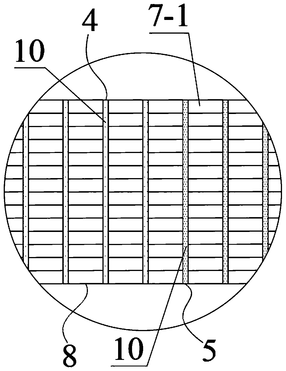
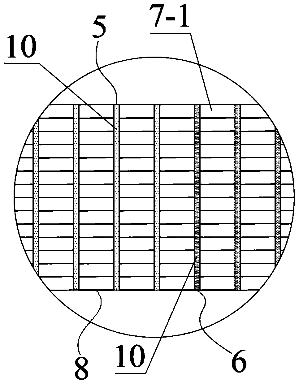
[0044] The structure of each strip-shaped plastic sheet 8 is the same, and it is all made up of the green segment 4 positioned at the inner side, the orange segment 5 positioned at the middle and the red segment 6 positioned at the outsid...


PUM


Abstract

The invention provides a mine tray for prejudging the magnitude of anchoring force on the basis of surface deformation and a monitoring method. According to the mine tray, a tray body comprises a spherical-crown-shaped part and a flat plate part; a deformation recognizing unit comprises four strip-shaped plastic thin pieces which form a cross shape and are attached to the surface of the spherical-crown-shaped part, one end of each strip-shaped plastic thin piece starts from the edge of an anchor rod hole, and the other end of each strip-shaped plastic thin piece extends to the edge of the spherical-crown-shaped part; each strip-shaped plastic thin piece is composed of a green section, an orange section and a red section, the surface of each strip-shaped plastic thin piece is coated with areflecting film material and covered with a fin unit, and the fin unit is composed of multiple rows of rectangular small plastic pieces distributed in the length direction of the strip-shaped plasticthin piece. The method includes the steps of calibrating the mine tray through a compression testing machine, installing mine trays produced in the same batch as the calibrated mine tray on site, andestimating the magnitude of the anchoring force. By means of the tray and the method, the stress conditions of a corresponding anchor rod or anchor cable can be conveniently and visually prejudged, and the labor intensity and monitoring cost of monitoring staff can be remarkably reduced.

Description

technical field [0001] The invention belongs to the technical field of anchoring support for coal mine roadways, and in particular relates to a mining tray and a monitoring method for predicting the magnitude of anchoring force based on surface deformation. Background technique [0002] As one of the rock mass deformation control technologies with the lowest economic cost, the most obvious technical benefits and the simplest operation process, the current bolt support technology plays an extremely important role in the fields of slope control, subway tunnels, underground mine construction, etc. The superiority is self-evident. The bolt support structure is usually composed of visible parts and invisible parts. The invisible parts are mainly rods and anchor nodes that go deep into the rock mass, and the visible parts are mainly exposed threaded sections of trays, nuts and bolts. Therefore, the invisible part has greater concealment, and its mechanical bearing state is often ...

Claims


Application Information

Patent Timeline
Patent Type & Authority Applications(China)
IPC IPC(8): E21D20/00E21F17/18
CPCE21D20/00E21F17/18
Inventor 冯晓巍
Owner CHINA UNIV OF MINING & TECH
Why Eureka
Try Eureka