Waste heat utilization system and method suitable for fluctuating heat load

A heat load and waste heat technology, applied in the direction of heat exchangers, indirect heat exchangers, heat exchanger types, etc., can solve problems such as ineffective utilization, achieve the effects of avoiding heat dissipation loss, improving waste heat utilization efficiency, and meeting demand fluctuations

Active Publication Date: 2021-01-08
ANGANG STEEL CO LTD
View PDF3 Cites 0 Cited by
  • Summary
  • Abstract
  • Description
  • Claims
  • Application Information

AI Technical Summary

Problems solved by technology

[0005] The technical problem to be solved by the present invention is to provide a waste heat utilization system and method suitable for fluctuating heat loads, which realizes the control of the amount of heat supplied by cooling users and heating users, and meets the demand fluctuations of users; The problem that the gas temperature after the first-stage compression of the compressor is too low and cannot be effectively utilized after waste heat recovery improves the waste heat utilization efficiency of the system

Method used


Image

  • Waste heat utilization system and method suitable for fluctuating heat load

Examples


Embodiment 1

[0027] Applicable to waste heat utilization systems with fluctuating heat loads to realize waste heat utilization methods, including:

[0028] Maximum cooling capacity mode:

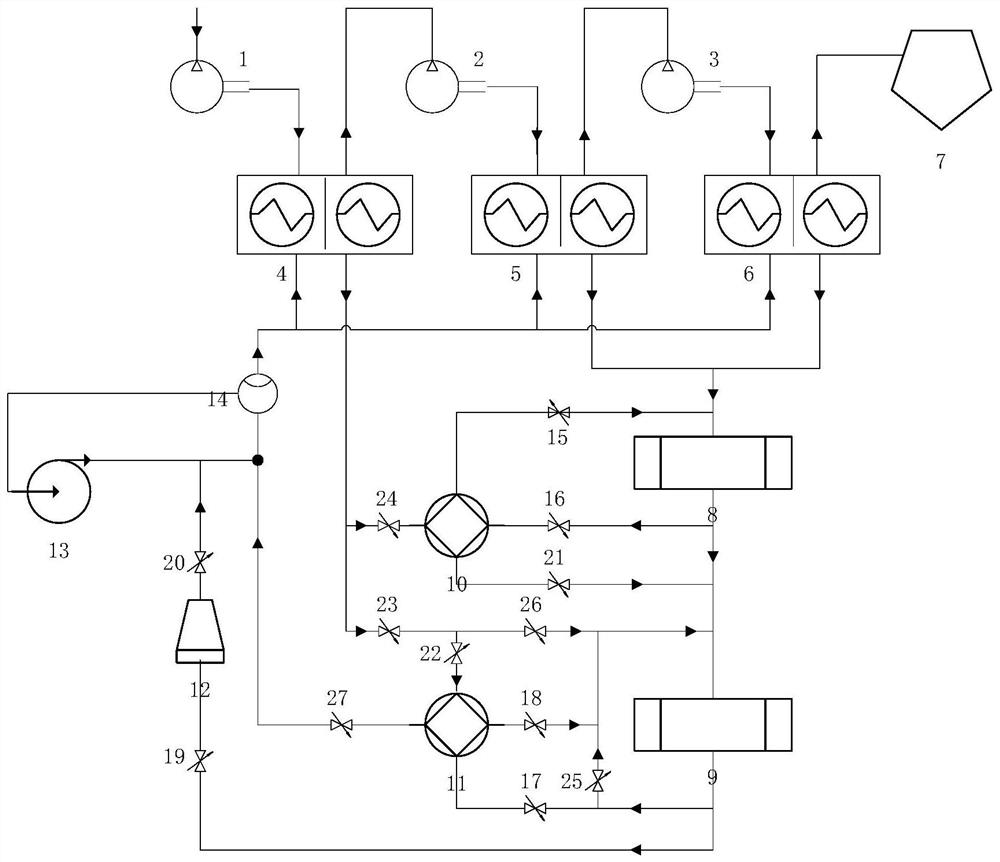
[0029] In the maximum cooling capacity operation mode, the switch valves 15, 19, 20, 21 are in the open state, the switch valves 18, 23, 26, 27 are in the closed state; the switch control valves 16, 24 are in the open state, and the switch control valves 17, 22 are in the open state. , 25 are in the closed state.

[0030] 150,000 Nm 3 / h The air at normal temperature and pressure reaches 95°C after being compressed by the first stage of the air compressor, and enters the first stage heat exchanger 4 to exchange heat with the cooling water at 35°C. After the heat exchange, the compressed air temperature is 40°C and enters the air compressor Two-stage compression, three-stage compression of the air compressor, the temperature of the second-stage compressed air and the third-stage compressed air can reach...

Embodiment 2

[0034] Applicable to waste heat utilization systems with fluctuating heat loads to realize waste heat utilization methods, including:

[0035] Maximum heat supply mode:

[0036] In the maximum heat supply operation mode, the on-off valves 18, 19, 20, 23, and 27 are in the open state, the on-off valves 15, 21 are in the closed state, and the on-off valve 26 is switchable; the on-off regulating valves 17, 22, and 25 are in the open state , the switch regulating valves 16, 24 are in the closed state.

[0037] 150,000 Nm 3 / h Normal temperature and normal pressure air passes through the first stage of the air compressor, and the temperature reaches 80°C, and enters the first stage heat exchanger 4 to exchange heat with 35°C cooling water. After the heat exchange, the compressed air temperature is 40°C and enters the air compressor Two-stage compression, three-stage compression of the air compressor, the temperature of the second-stage compressed air and the third-stage compresse...


PUM


Abstract

The invention relates to a waste heat utilization system suitable for the fluctuating heat load. The system comprises an air compressor first-stage compression, an air compressor second-stage compression, an air compressor third-stage compression, a first-stage heat exchanger, a second-stage heat exchanger, a third-stage heat exchanger, an oxygen generator, a refrigeration user, a heat supply user, a 1# heat pump unit, a 2# heat pump unit, a cooling tower, a water supplementing pump and a flow meter. Waste heat of cooling water of an air compressor is directly utilized, and intermediate heatexchange equipment is reduced, thereby preventing excessive heat dissipation loss of the system, and improving the heat efficiency of the system; through flow control over driving heat source fluid and heating fluid of the 1# heat pump unit and the 2# heat pump unit, control over the heat supply amount of the refrigeration user and the heat supply user is achieved, and the demand fluctuation of the users is met; and meanwhile, the problem that after first-stage compression of the air compressor, the temperature of gas is low, and waste heat cannot be effectively utilized after being recycled is solved, and the waste heat utilization efficiency of the system is improved.

Description

technical field [0001] The invention relates to the field of waste heat recovery, in particular to a waste heat utilization system and method suitable for fluctuating heat loads. Background technique [0002] Iron and steel enterprises need a large amount of high-purity oxygen, nitrogen and other energy media in the process of smelting and production, so large iron and steel enterprises usually have their own oxygen production process, and there are multiple air compressors in the oxygen production process; when the air compressor is running , the electric energy actually consumed to increase the air potential energy only accounts for a very small part in the total electricity consumption, about 15%. About 85% of the electricity consumption is converted into heat and exists in the compressed gas, which is discharged into the air through air cooling or water cooling. If this part of the waste heat of the compressed gas is recovered and used for heating in winter or cooling i...

Claims


Application Information

Patent Timeline
Patent Type & Authority Patents(China)
IPC IPC(8): F28D21/00
CPCF28D21/0007
Inventor 徐伟倪健勇马光宇张天赋贾振刘芳陈鹏胡绍伟王飞王永
Owner ANGANG STEEL CO LTD
Why Eureka
Try Eureka