Raster imaging system and its scanning method

A technology of raster imaging and scanning method, which is applied in the field of raster imaging system and its scanning, and can solve the problems of the hazard of the measured object, the inability to process the raster, and the time consuming.

Active Publication Date: 2022-04-29
TSINGHUA UNIV
View PDF6 Cites 0 Cited by
  • Summary
  • Abstract
  • Description
  • Claims
  • Application Information

AI Technical Summary

Problems solved by technology

A larger imaging field of view also means a larger grating group, and the current grating manufacturing process cannot be processed in one go
Similarly, for the traditional grating imaging method, the measured object is generally scanned by moving relative to the grating, and the scanning process is more complicated; in addition, the traditional phase step scanning is time-consuming, and the radiation dose is high, which is harmful to the measured object.

Method used


Image

  • Raster imaging system and its scanning method
  • Raster imaging system and its scanning method
  • Raster imaging system and its scanning method

Examples


Embodiment 1

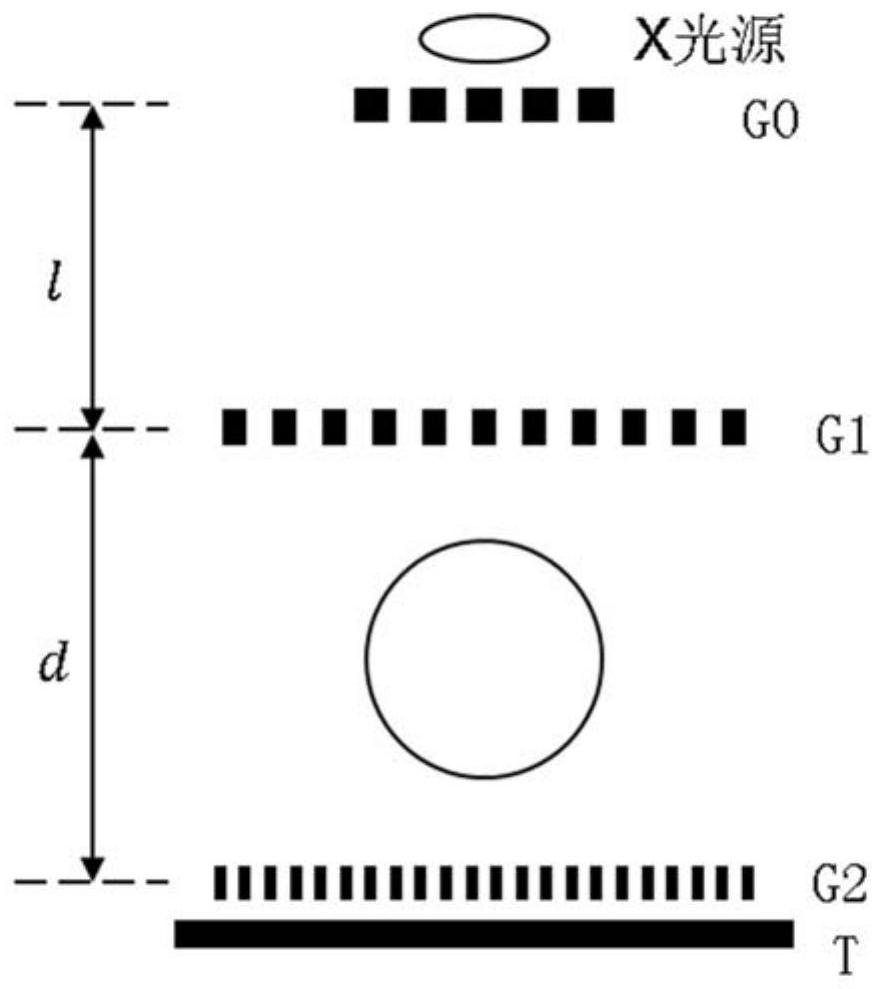
[0049] One aspect of the present invention proposes a raster imaging system such as figure 1 As shown, the system includes a source grating G0, a first grating G1 and a second grating G2 arranged sequentially along the optical path, wherein: the source grating G0 is used to convert the incoherent light emitted by the light source into coherent light, and a plurality of first The first grating G1 composed of grating units is used to obtain the first image after the coherent light passes through the first grating G1; and the second grating G2 composed of multiple second grating units is used to obtain the first image. Second imaging; wherein, an imaging irradiation position is set between the first grating G1 and the second grating G2. In other words, the source grating G0 , the first grating G1 and the second grating G2 form an optical path and constitute a system.

[0050] Specifically, as an embodiment of the present invention, the light source is an X-ray light source, and ...

Embodiment 2

[0101] One aspect of the present invention proposes a grating imaging system, the system includes a source grating G0, a first grating G1 and a second grating G2 arranged in sequence along the optical path, wherein: the source grating G0, the first grating G1 and the second grating G2 At least one of them is a curved grating, and an imaging irradiation position is set between the first grating G1 and the second grating G2.

[0102] As an embodiment of the present invention, such as Figure 8 As shown, where the system includes the source grating G0, the first grating G1 and the second grating G2 arranged sequentially along the optical path to form the grating group of the system, wherein: the source grating G0 is used to convert the incoherent light emitted by the light source into coherent light; the first grating G1, used to obtain a first image after the coherent light passes through the first grating G1; and the second grating G2, used to operate on the first image to obta...

Embodiment 3

[0149] Another aspect of the present invention proposes a grating imaging system, which is characterized in that the system includes a source grating G0, a first grating G1, and a second grating G2 arranged sequentially along the optical path, wherein:

[0150] The first grating G1 includes a plurality of first grating units that are spliced ​​in dislocation; and / or the second grating G2 includes a plurality of second grating units that are spliced ​​in dislocation,

[0151] Wherein, the plurality of first grating units or the plurality of second grating units are displaced along the grating directions of the corresponding first grating units or the second grating units.

[0152] Specifically, as an embodiment of the present invention, such as Figure 10 As shown, the light source is an X-ray light source, and the X-ray beam emitted by the light source passes through the source grating G0 to generate a series of partially coherent linear lights. In addition, the X light sourc...


PUM


Abstract

The invention discloses a grating imaging system and a scanning method thereof. The system includes a source grating (G0), a first grating (G1) and a second grating (G2) arranged in sequence along an optical path, wherein: the source grating (G0), the second grating At least one of the first grating (G1) and the second grating (G2) is a curved grating, and an imaging irradiation position is set between the first grating (G1) and the second grating (G2). While maintaining good image quality, the overall scanning time is reduced to a level close to that of clinical X-ray chest films, and the radiation dose is well controlled; in general, the large-field raster imaging system has a large imaging field of view. , fast scanning speed, low radiation dose and other advantages and characteristics.

Description

technical field [0001] The invention relates to the technical field of optical imaging, in particular to a grating imaging system and a scanning method thereof. Background technique [0002] X-ray grating phase-contrast imaging technology can realize local structure resolution on micron or submicron level, which is a good supplement to traditional X-ray imaging technology. This technology can simultaneously extract three kinds of information of absorption, phase contrast and dark field images, and is suitable for the distinction between low atomic number and low density substances, especially for biological soft tissue structures including breast. In order to obtain better image quality, grating imaging technology usually acquires data by phase stepping. This method refers to displacing one of the gratings along the direction perpendicular to the grid line of the grating in one or more cycles, so as to obtain the displacement curve before and after placing the object. [0...

Claims


Application Information

Patent Timeline
Patent Type & Authority Patents(China)
IPC IPC(8): A61B6/06
CPCA61B6/06A61B6/44
Inventor 张丽陈志强高河伟李新斌邢宇翔
Owner TSINGHUA UNIV
Why Eureka
Try Eureka