A hydraulic nut shredder

A hydraulic and nut technology, applied in the field of hydraulic equipment, can solve problems such as scattering, waste of time by chemical methods, unsuitable for dismantling a large number of nuts, etc.

Active Publication Date: 2021-04-23
NANJING YUZHI INTELLIGENT TECH CO LTD
View PDF9 Cites 2 Cited by
  • Summary
  • Abstract
  • Description
  • Claims
  • Application Information

AI Technical Summary

Problems solved by technology

[0002] In the dismantling of assembled steel structures, the bolts must be dismantled first, and the commonly used carbon steel bolts will be seriously rusted after a long period of use. In this case, chemical and mechanical methods are usually used to disassemble the bolts. Two, the chemical method is more time-consuming and not suitable for dismantling a large number of nuts. At present, the mechanical shredding method is commonly used. The mechanical shredding method uses an external machine to directly cut off the nuts to achieve the purpose of dismantling. The machine has the following defects: 1. The commonly used shredding machine usually uses a fixed frame to be directly sleeved on the nut, and the cutting head is directly squeezed and cut off the side of the nut through the hydraulic drive, which requires a large thrust of the hydraulic cylinder to realize mechanical cutting. , but a large amount of shearing will reduce the service life of the oil cylinder. 2. The nuts are prone to scatter after being cut off. If they are at high altitude, the scattered nuts will cause hidden dangers of injury. 3. When the nuts are seriously rusted, they will appear , after the nut is cut off, one side will be separated from the bolt, and the other side will adhere to the bolt due to oxidation, so it needs to be cleaned manually with the help of tools. Therefore, the present invention provides a hydraulic nut shredder

Method used


Image

  • A hydraulic nut shredder
  • A hydraulic nut shredder
  • A hydraulic nut shredder

Examples


Embodiment approach

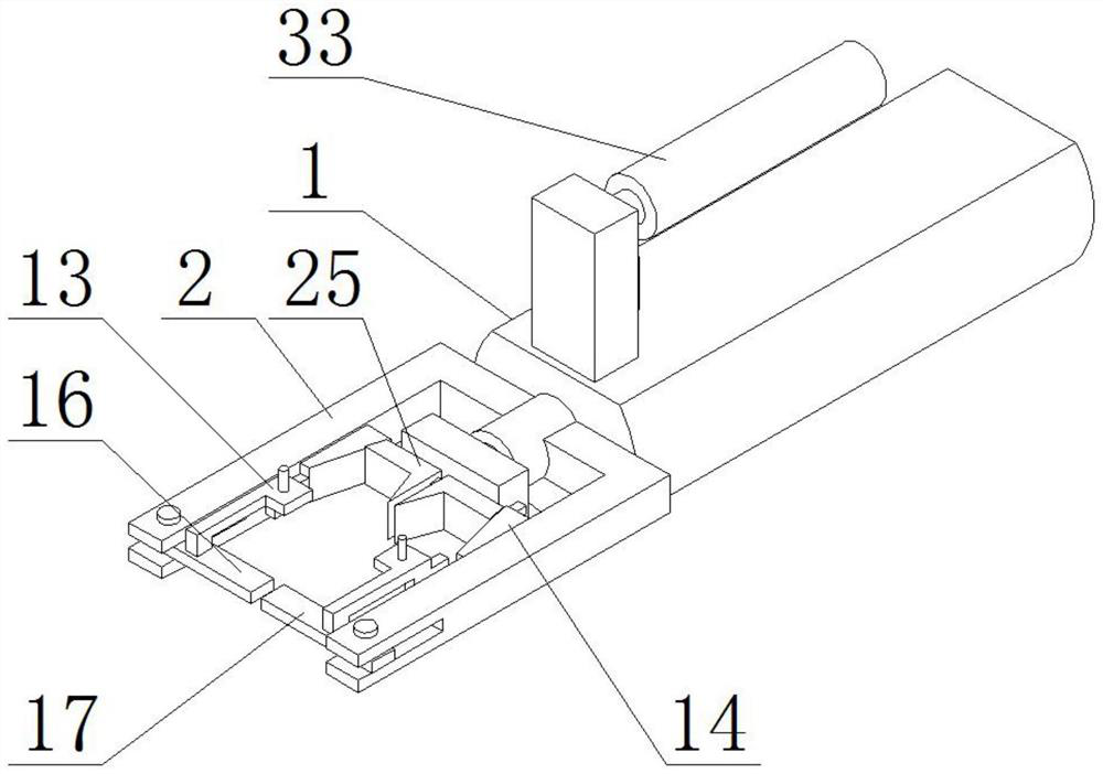
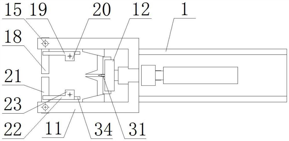
[0029]As a preferred embodiment of the present invention, a joint is provided on the upper limit bit rod 20 and the lower limit bit rod 23, the joint being connected by a wire and a current amplifier 5.

[0030]As a preferred embodiment of the present invention, one side of the upper connecting rod 19 and the lower connecting rod 22 is provided with diaphragm 34.

[0031]As a preferred embodiment of the present invention, the hydraulic motor 6 is connected to the hydraulic cylinder 7 and the hydraulic tank 8 via a line.

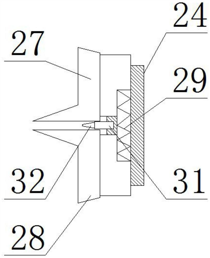
[0032]As a preferred embodiment of the present invention, the gap between the upper knife 27 and the lower knife 28 is 0.1 to 0.5 mm.

[0033]As a preferred embodiment of the present invention, the control button includes a hydraulic thrust switch, a hydraulic return switch, and a current amplifier switch, the control button being connected to the hydraulic cylinder 7 and the current amplifier 5, the battery 30 by electricity The box is connected to the hydraulic motor 6 and t...


PUM


Abstract

The invention discloses a hydraulic nut shredder, which comprises a fuselage, a machine head and a control box. The fuselage includes a casing, a hydraulic motor, a hydraulic oil cylinder, a hydraulic oil tank, a storage battery and a current amplifier. There is a fixed sleeve, one end of the casing is provided with a rotary sleeve, the hydraulic cylinder is sleeved at one end of the fixed sleeve, and the hydraulic cylinder, hydraulic motor, hydraulic oil tank, battery and current amplifier are sleeved from left to right Located in the fixed casing, the machine head includes a crushing fixed frame, a combined pressing head and a self-locking discharge mechanism, and the crushing fixed frame is provided with a tapered guide rail and a rotary pin. The indenter of the cutting machine of the present invention adopts a docking type, with a built-in laser transmitter, which produces a shallow indentation by pressing the indenter on one side of the nut, and heats and softens the bottom of the indentation through the built-in laser irradiation, reducing the propulsion resistance of the hydraulic cylinder. This can quickly break the nut and prolong the service life of the hydraulic components.

Description

Technical field[0001]The present invention relates to the technical field of hydraulic instruments, in particular a hydraulic nut breaking machine.Background technique[0002]In the dismantling of the assembled steel structure, first remove the bolts, and the commonly used carbon steel bolts will seriously rust after long-term use, in which case the disassembly of bolts is usually used chemical method and mechanical method. Two kinds of chemical methods are not suitable for a large number of nut dismantles. It is often used to mechanical breaking law. The mechanical breaking method is to directly reach the disassembly by means of external machines, but this nut is broken. The machine has the following defects: 1. Commonly used breaking machines typically use the fixed frame directly to the nut, directly extruded the nut side by hydraulic drive cutting, which requires the hydraulic cylinder to output a large thrust to achieve mechanical cutting. However, a large number of shearns reduc...

Claims


Application Information

Patent Timeline
Patent Type & Authority Patents(China)
IPC IPC(8): B23D15/00B23D33/00B23P25/00B23Q11/00
CPCB23D15/00B23D33/00B23P25/006B23Q11/0064
Inventor 胡梦茹
Owner NANJING YUZHI INTELLIGENT TECH CO LTD
Why Eureka
Try Eureka