Multifunctional driver and new energy vehicle

A new energy vehicle and drive technology, applied in the direction of electric vehicles, control drive, vehicle components, etc., can solve the problems affecting the efficiency and reliability of the whole vehicle, the single function of functional modules, and the high price of the drive, so as to improve the ability of anti-electromagnetic interference , efficient heat dissipation, and convenient after-sales maintenance

Inactive Publication Date: 2020-03-27
GREE ELECTRIC APPLIANCES INC
View PDF5 Cites 1 Cited by
  • Summary
  • Abstract
  • Description
  • Claims
  • Application Information

AI Technical Summary

Problems solved by technology

However, most of the drivers on the market currently adopt a separate structure, with low integration, single function of each functional module, and complicated hard-wire connection, resulting in high price of the driver and large overall size, which affects the efficiency and reliability of the whole vehicle.

Method used


Image

  • Multifunctional driver and new energy vehicle
  • Multifunctional driver and new energy vehicle
  • Multifunctional driver and new energy vehicle

Examples


Embodiment 1

[0023] Embodiment 1, a multifunctional driver.

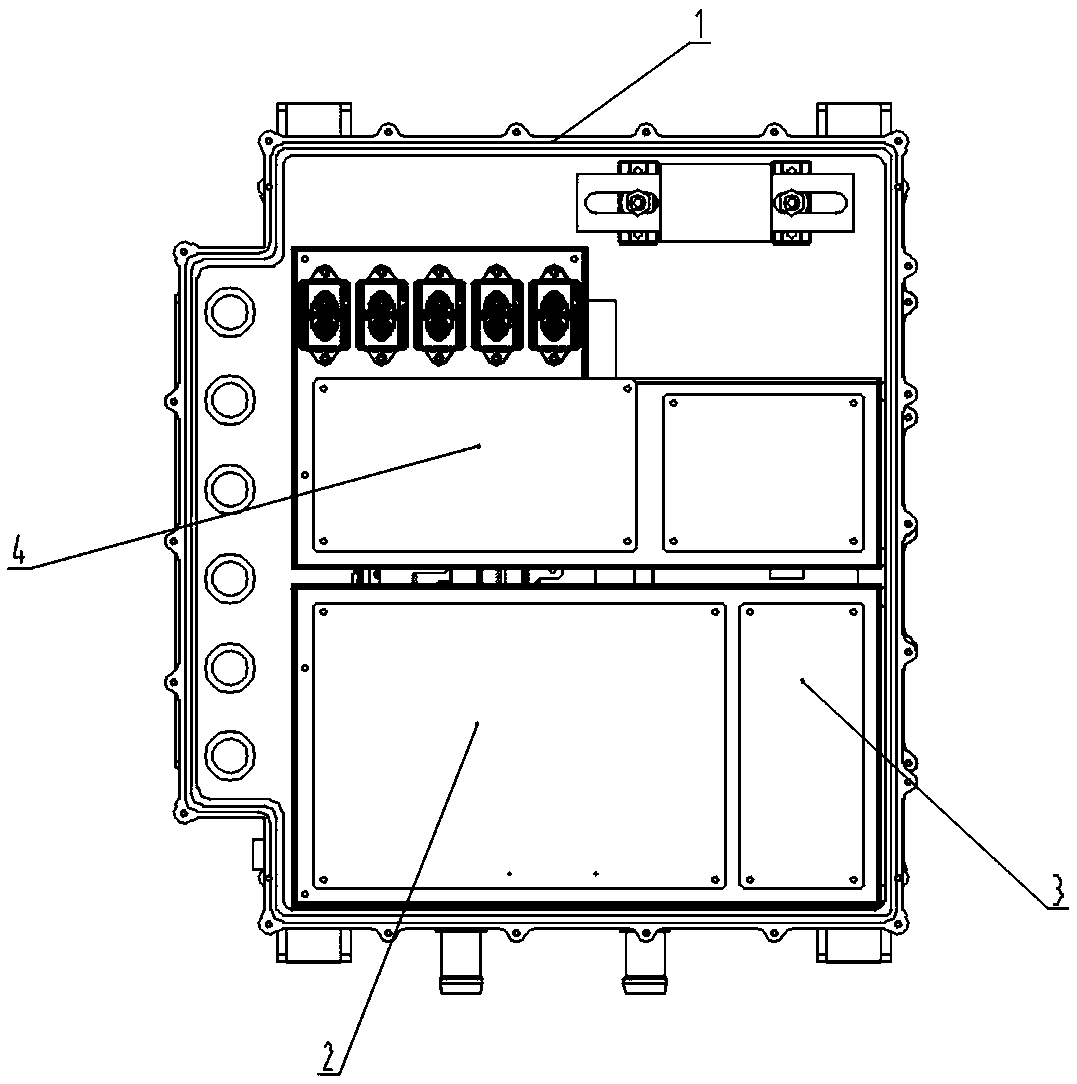
[0024] A multi-functional driver in this embodiment, the driver includes a driver housing 1, inside the driver housing 1 is provided with a plurality of functional modules, the functional modules are separately installed in the driver housing 1, and the driver housing 1 is provided with an upper The cavity and the lower cavity are provided with a heat dissipation plate between the upper cavity and the lower cavity. The heat dissipation plate includes a plurality of heat dissipation channels 11. The top layer of the upper cavity is installed with an integrated main control module 2. The integrated main control module 2 It includes motor control module, oil pump control module and air pump control module.

[0025] The motor control module, the oil pump control module and the air pump control module are all weak current control circuits, which are integrated in the integrated main control module 2, which is more conducive to the ra...

Embodiment 2

[0036] Embodiment 2, a kind of new energy vehicle.

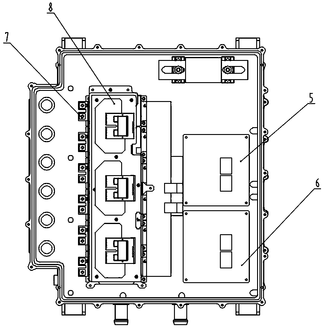
[0037] This embodiment provides a new energy vehicle. The new energy vehicle includes the multifunctional driver described in Embodiment 1, the main drive motor, the oil pump motor, the air pump motor, the air pump, and the oil pump. The main drive motor and the main drive motor drive module 8 pass through the conductor Electrically connected, the oil pump motor and the oil pump motor drive module 5 are electrically connected through a conductor, the air pump motor and the air pump motor drive module 6 are electrically connected through a conductor, the air pump is connected to the air pump motor, and the oil pump is connected to the oil pump motor.

[0038] The control chip in the driver controls the operation of the main drive motor through the main drive motor drive module 8, controls the operation of the oil pump through the oil pump motor drive module 5, and controls the operation of the air pump through the air pump mot...


PUM


Abstract

The invention discloses a multifunctional driver and a new energy vehicle. The driver comprises a driver shell. Multiple functional modules are arranged in the driver shell. The function modules are installed in the driver shell in a separated mode. An upper cavity and a lower cavity are formed in the driver shell, a heat dissipation plate is arranged between the upper cavity and the lower cavity,a plurality of heat dissipation flow channels are formed in the heat dissipation plate, an integrated main control module is installed on the top layer of the upper cavity, and a motor control module, an oil pump control module and an air pump control module are arranged on the integrated main control module. According to the invention, the function modules in the driver are installed in a separated manner. Control circuits of the functional modules are integrated on the integrated main control module. The heat dissipation plate integrated with the plurality of heat dissipation flow channelsis arranged in the middle of a driver, so that the anti-electromagnetic interference capability and the heat dissipation performance of the driver are improved, the reliability of the driver is improved, and meanwhile, all functional modules in the driver are arranged more flexibly and are convenient to assemble and maintain.

Description

technical field [0001] The invention relates to the technical field of new energy vehicles, in particular to a multifunctional driver and a new energy vehicle. Background technique [0002] As the country pays more and more attention to energy and environmental protection issues, the development of new energy electric vehicles is gradually accelerating, and the main motor drivers of new energy vehicles have also been widely used. In the actual application process of drives, OEMs have higher and higher requirements on the cost, power density and reliability of drives. However, most of the drivers on the market currently adopt a separate structure, with low integration, and each functional module has a single function, requiring complicated hard-wired connections, resulting in high prices for the driver, and a large overall size, which affects the efficiency and reliability of the vehicle. Contents of the invention [0003] The purpose of the present invention is to overcom...

Claims


Application Information

Patent Timeline
Patent Type & Authority Applications(China)
IPC IPC(8): B60L15/00B60R16/02H05K7/20
CPCB60L15/00B60R16/02H05K7/20845
Inventor 牛高产陈广辉游健康
Owner GREE ELECTRIC APPLIANCES INC
Why Eureka
Try Eureka