Conveying device for liquid pesticide production and filling equipment with delivery device
A conveying device and pesticide technology, applied in liquid bottling, liquid handling, transportation and packaging, etc., can solve the problems of easy tilting or even dumping, worker injury, pesticide waste, etc., and achieve the effect of increasing the stability of motion
- Summary
- Abstract
- Description
- Claims
- Application Information
AI Technical Summary
Problems solved by technology
Method used
Image
Examples
Embodiment 1
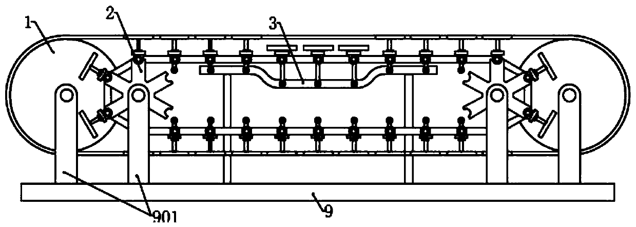
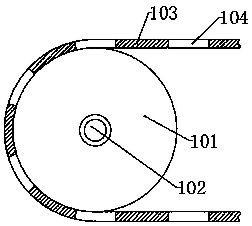
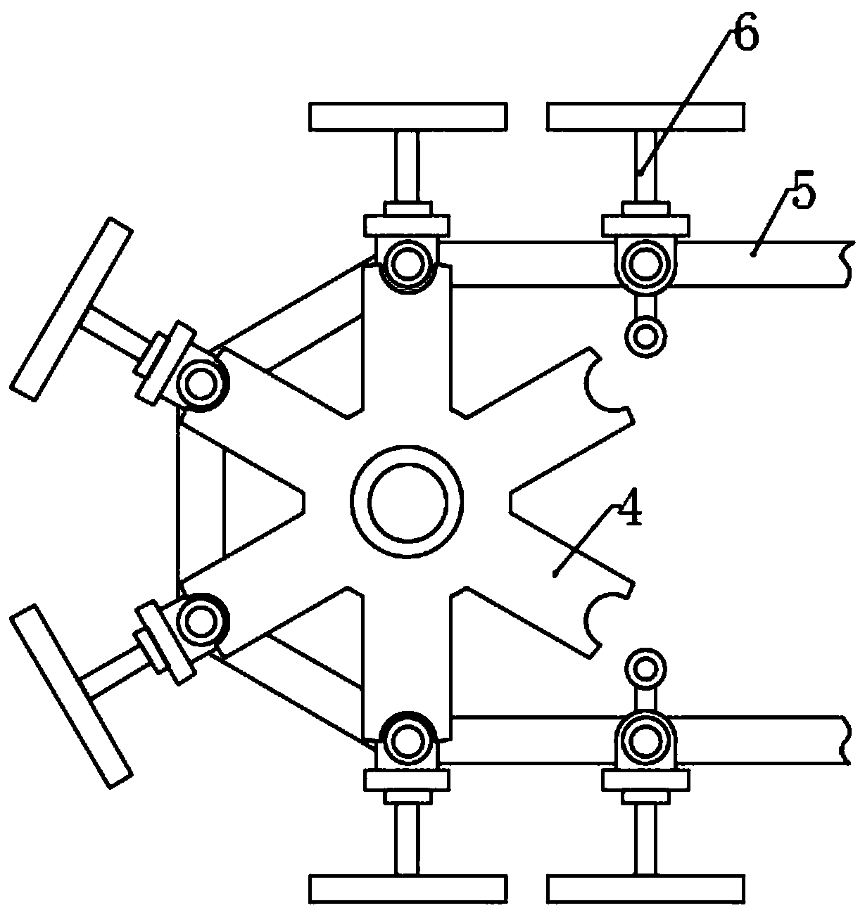
[0039] Please refer to the attachedfigure 1 , the present invention provides a technical solution: a conveying device for liquid pesticide production and filling equipment with the device, including a base 9, a pulley mechanism 1, a sprocket mechanism 2 and a guide rail 3, characterized in that the base 9 is provided with a plurality of supporting rods 901 corresponding to the pulley mechanism 1, the sprocket mechanism 2 and the guide rail 3. The pulley mechanism 1 includes a conveyor belt 103 and four rotating wheels 101, and the four rotating wheels 101 are respectively arranged on On both sides of the conveyor belt 103, two rotating wheels 101 located on the same side are coaxially arranged, and the center of the rotating wheels 101 is fixed with a pulley shaft 102, and the pulley shaft 102 is rotationally connected with the corresponding support rod 901. A plurality of bottle grooves 104 are evenly arranged along the length direction on the conveyor belt 103, and the sprock...
Embodiment 2
[0046] The structure and working principle of this embodiment are basically the same as those of Embodiment 1, the difference is that a shaft sleeve 611 is rotatably connected to the connecting shaft 609, and the slot 403 of the chain plate 5 is connected to the connecting shaft through the shaft sleeve 611. 609 corresponds to the connection. When the slot 403 on the fixed plate 402 clamps the sleeve 611 and drives it to move, the sleeve 611 can rotate relative to the connecting shaft 609, preventing the side wall of the slot 403 from directly contacting the connecting shaft 609. The relative movement between the card slot 403 and the connecting shaft 609 produces abrasion.
Embodiment 3
[0048] The structure and working principle of this embodiment are basically the same as those of Embodiment 2, the difference is that the guide shaft 606 is also rotatably connected with a roller 607, and is connected to the guide rail 3 through the roller 607, when the guide shaft 606 enters the guide rail 3, the guide shaft 606 is in contact with the side wall of the guide rail 3 through the roller 607, and the sliding between the guide shaft 606 and the guide rail 3 is changed into a rolling between the roller 607 and the guide rail 3, so that the moving assembly 6 is relatively opposite to the guide rail 3 movement is more flexible.
PUM
 Abstract
Description
Claims
Application Information
 - R&D
- Intellectual Property
- Life Sciences
- Materials
- Tech Scout
- Unparalleled Data Quality
- Higher Quality Content
- 60% Fewer Hallucinations
Browse by: Latest US Patents, China's latest patents, Technical Efficacy Thesaurus, Application Domain, Technology Topic, Popular Technical Reports.
© 2025 PatSnap. All rights reserved.Legal|Privacy policy|Modern Slavery Act Transparency Statement|Sitemap|About US| Contact US: help@patsnap.com


