
Continuous annealing furnace bottom cover plate quick disassembling and assembling device and disassembling and assembling method

A continuous annealing furnace and cover plate technology, which is applied in furnaces, heat treatment furnaces, furnace types, etc., can solve the problems of furnace bottom cover plate jamming, furnace bottom cover plate alignment position is not easy to determine, and hurt people, etc., to achieve shortening Installation time, shortening the time for dismantling the furnace bottom cover, and the effect of protecting the seal

Active Publication Date: 2020-03-27
HANDAN IRON & STEEL GROUP +1
View PDF8 Cites 2 Cited by
  • Summary
  • Abstract
  • Description
  • Claims
  • Application Information

AI Technical Summary

Problems solved by technology

This method has the following problems: First, the furnace bottom cover needs to be accurately placed in the furnace shell slot during the installation of the bottom cover, and the alignment position of the furnace bottom cover is not easy to determine, and the position of the trolley needs to be manually adjusted repeatedly, which is time-consuming and laborious The second is that the furnace bottom cover plate is prone to deformation due to the influence of thermal expansion and cold contraction, causing the furnace bottom cover plate to be stuck on the furnace shell and cannot be disassembled smoothly. Tools such as crowbars are needed, and there is a danger of injury; The lifting distance of the furnace bottom cover plate is not easy to grasp, and the seal between the furnace bottom cover plate and the opening of the furnace shell is easily squeezed and damaged

Method used


Image

  • Continuous annealing furnace bottom cover plate quick disassembling and assembling device and disassembling and assembling method
  • Continuous annealing furnace bottom cover plate quick disassembling and assembling device and disassembling and assembling method
  • Continuous annealing furnace bottom cover plate quick disassembling and assembling device and disassembling and assembling method

Examples


Embodiment Construction

[0025] Below in conjunction with accompanying drawing, the present invention will be further described by examples.

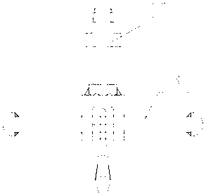
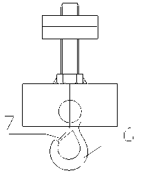
[0026] Refer to attached Figure 1-6 , a continuous annealing furnace furnace bottom cover quick disassembly device, including furnace bottom cover 1, guide chain 2, fixed bracket 3, fastening bolt 5, hook 6, reverse jacking wire 9, card slot 14 and furnace shell 15. Four card slots 14 are evenly fixed around the furnace shell 15, and a fastening bolt 5 is respectively installed on each card slot 14. The fastening bolt 5 includes a screw rod and a bolt head, and the screw thread of the fastening bolt 5 Connected on the card slot 14, the bolt head of the fastening bolt 5 is an inverted U-shaped structure, the bolt head of the fastening bolt 5 is provided with a hook 6, and a guide chain 2 is suspended on the hook 6 of each fastening bolt 5 , the lower end of the guide chain 2 is connected to the fixed bracket 3, the fixed bracket 3 is fixed on the furnace botto...


PUM


Abstract

The invention relates to a continuous annealing furnace bottom cover plate quick disassembling and assembling device and disassembling and assembling method, and belongs to the technical field of cold-rolling strip steel production equipment in the metallurgical industry. According to the technical scheme, the periphery of a furnace shell (15) is fixedly and uniformly provided with four clamping grooves (14), each clamping groove (14) is provided with a corresponding fastening bolt (5), a corresponding screw of each fastening bolt (5) is in threaded connection with the corresponding clamping groove (14), hooks (6) are arranged on the bolt heads of the fastening bolts (5) correspondingly, a corresponding guide chain (2) is hung on the corresponding hook (6) of each fastening bolt (5), the lower ends of the guide chains (2) are connected to a fixing support (3), the fixing support (3) is fixed to a furnace bottom cover plate (1), and a reverse jackscrew (9) is in threaded connection withthe furnace shell (15) close to the furnace bottom cover plate (1). The device has the beneficial effects that the furnace bottom cover plate can be quickly disassembled and assembled, the time losscaused by furnace bottom cover plate disassembling and assembling is reduced, and the accident or maintenance treating time is shortened.

Description

technical field [0001] The invention relates to a device and a method for quickly disassembling and disassembling a bottom cover plate of a continuous annealing furnace, and belongs to the technical field of cold-rolled steel strip production equipment in the metallurgical industry. Background technique [0002] The continuous annealing furnace adopts a fully enclosed furnace structure. The furnace is filled with a reducing atmosphere of hydrogen and nitrogen mixed to form a protective gas, which is used to isolate the air and prevent the strip steel from being oxidized in the continuous annealing furnace. When encountering equipment maintenance in the continuous annealing furnace or production accidents in the furnace, it is usually necessary to disassemble the furnace bottom cover plate, cool down and ventilate the annealing furnace, and then arrange maintenance personnel to enter the annealing furnace for equipment maintenance or accident handling. After completion or aft...

Claims


Application Information

Patent Timeline
Patent Type & Authority Applications(China)
IPC IPC(8): C21D9/56C21D1/26C21D1/74
CPCC21D9/562C21D9/561C21D1/26C21D1/74Y02P10/20
Inventor 周恒龙贺有刘志利王智增郑占领任力华张猛
Owner HANDAN IRON & STEEL GROUP
Learn More