Drill float valve with automatic protection

An automatic protection and drilling tool technology, applied in earth-moving drilling, wellbore/well components, flushing wellbore, etc., can solve problems such as driving up drilling costs, difficult assembly, lax shut-down, etc., to reduce drilling risks and production. Cost, use and maintenance costs are low, the effect of prolonging the service life

Active Publication Date: 2020-05-19
东营市创元石油机械制造有限公司
View PDF7 Cites 0 Cited by
  • Summary
  • Abstract
  • Description
  • Claims
  • Application Information

AI Technical Summary

Problems solved by technology

[0004] At present, most of the commonly used floating valves for drilling tools have unreasonable structures. The mud directly erodes the seals and the springs have no limit protection. During the maintenance process, the assembly is difficult and the efficiency is low. During the use, the seal often fails, the spring is prone to fatigue, the failure rate is high, the reliability is low, and the service life is short, which greatly pushes up the drilling cost. When drilling operations, reverse circulation, well kick or blowout occur in the well, the spring fails, and the arrow valve core is not closed tightly, which loses the function of preventing drilling fluid from flowing back and preventing sediment from entering the drill string, and cannot achieve the purpose of preventing plugging and blowout , there is a great potential safety hazard, which puts the drilling operation at great risk, seriously threatens the safety of relevant personnel and facilities, and cannot meet the increasingly harsh downhole working conditions.

Method used


Image

  • Drill float valve with automatic protection
  • Drill float valve with automatic protection
  • Drill float valve with automatic protection

Examples


Embodiment 1

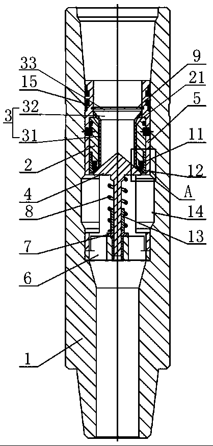
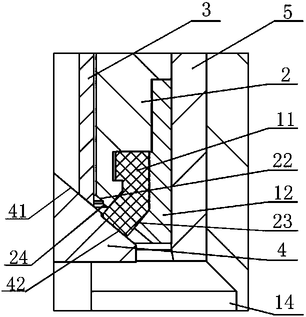
[0032] Reference figure 1 with figure 2 , A drilling tool float valve with automatic protection, comprising a valve body 1, a valve seat 2, a valve sleeve 5, a protection cylinder 3 and a mushroom head valve core 4. .

[0033] Among them, a valve sleeve 5 and a shunt seat 6 are respectively installed in the valve body 1 from top to bottom. The shunt seat 6 and the valve sleeve 5 are detachably connected together, and the shunt seat 6 sits on the inner hole step of the valve body 1. The sleeve 5 sits on the shunt seat 6, a guide spring seat 7 is also installed in the middle of the shunt seat 6, and a spring 8 is sleeved on the guide spring seat 7, through which the mushroom head valve core 4 can be reset. An elastic retaining ring 9 is fixed on the inner wall of the inner cavity of the valve sleeve 5 at the upper part, and the upward position of the protective cylinder 3 can be defined by the elastic retaining ring 9.

[0034] The valve seat 2 is arranged in the inner cavity of t...

Embodiment 2

[0038] Others are basically the same as Embodiment 1. The difference is that a limit sleeve 13 is provided on the upper end of the guide spring seat 7, and the limit sleeve 13 can be used to limit the lowermost position of the mushroom head valve core 4 to move down. Ensure the smooth passage of mud, on the other hand, protect the spring 8 from fatigue damage and prolong the service life.

[0039] In addition, a slow flow chamber 14 with a diameter larger than the diameter of the valve sleeve 5 is provided in the valve sleeve 5 below the valve seat 2. The valve sleeve 5 is provided with an opening that communicates with the slow flow chamber 14. The buffering effect prevents the hard impact of the mud.

[0040] An r-shaped sealing ring 15 sealed with the valve body 1 is provided on the valve sleeve 5.

[0041] The guide spring seat 7 is fixed in the middle of the shunt seat 6, and the middle of the guide spring seat 7 is provided with a guide cavity for the mushroom head valve core ...


PUM


Abstract

The invention discloses a drilling tool float valve with an automatic protection function. The drilling tool float valve comprises a valve body, a valve sleeve, a valve seat, a protective cylinder anda mushroom-head valve element, wherein a limiting sleeve is arranged below the mushroom-head valve element, on one hand, it is guaranteed that a mud channel is smooth, and on the other hand, a springis protected against fatigue failure; the protective cylinder is of a floating structure, the protective cylinder can be lowered to form a protective cavity after the mud channel is opened so as to effectively protect a sealing ring, direct impact of mud is prevented, and the service life of the sealing ring can be prolonged; and when the sealing ring is compressed to a set amount, a lower conical limiting surface at the lower end of the valve seat is attached to an upper conical surface of the mushroom-head valve element together to enable the sealing ring to be protected, too large pressureis prevented from damaging the sealing ring, and the service life of the sealing ring and the service life of the spring are prolonged.

Description

Technical field [0001] The invention relates to the technical field of internal blowout prevention tools for oil industry drilling, in particular to a drilling tool float valve with automatic protection. Background technique [0002] In oil, natural gas and other drilling and workover operations, in order to prevent the mud in the annulus from returning to the drill string and spraying onto the drill floor when connecting a single root or tripping, at the same time, to prevent the underlying fluid from being under formation pressure Under the action of the drilling tool, overflow, gush or blowout occurs when entering the drilling tool, and a drilling tool float valve is connected at the bottom of the drill string. [0003] Commonly used drilling tool float valves include arrow type drilling tool float valve and plate type drilling tool float valve. When the pump is turned on, the mud pressure pushes the arrow valve core to move down or the valve plate flips to open the mud channel....

Claims


Application Information

Patent Timeline
Patent Type & Authority Patents(China)
IPC IPC(8): E21B21/10
CPCE21B21/10
Inventor 朱怀军田皎雨王笑笑田相录
Owner 东营市创元石油机械制造有限公司
Why Eureka
Try Eureka