
Compression ignition jet ignition combustion system and combustion control method

A combustion system and control method technology, applied in the direction of fuel injection control, electrical control, charging system, etc., can solve the problems of difficult ignition and start-up of turbulent jet flow, high emission of nitrogen oxides, etc., to achieve improved combustion robustness, stable combustion, The effect of low combustion temperature

Active Publication Date: 2020-03-27
TSINGHUA UNIV
View PDF5 Cites 11 Cited by
  • Summary
  • Abstract
  • Description
  • Claims
  • Application Information

AI Technical Summary

Problems solved by technology

[0006] The embodiment of the present invention provides a compression ignition jet ignition combustion system and a combustion control method, which are used to solve the problem that the spark ignition in the existing combustion system is affected by the lean burn limit, which is prone to large cycle fluctuations, and the turbulent jet ignition is difficult to start. , high nitrogen oxide emissions defects

Method used


Image

  • Compression ignition jet ignition combustion system and combustion control method
  • Compression ignition jet ignition combustion system and combustion control method
  • Compression ignition jet ignition combustion system and combustion control method

Examples


Embodiment Construction

[0045] Embodiments of the present invention will be further described in detail below in conjunction with the accompanying drawings and examples. The following examples are used to illustrate the present invention, but should not be used to limit the scope of the present invention.

[0046] In the description of the present invention, unless otherwise specified, the meanings of "plurality" and "several" are two or more. The orientation or positional relationship indicated by the terms "upper", "lower", "left", "right", "inner", "outer", "front end", "rear end", "head", "tail" etc. is Based on the orientation or positional relationship shown in the drawings, it is only for the convenience of describing the present invention and simplifying the description, and does not indicate or imply that the referred device or element must have a specific orientation, be constructed and operated in a specific orientation, and therefore cannot be understood To limit the present invention. ...


PUM


Abstract

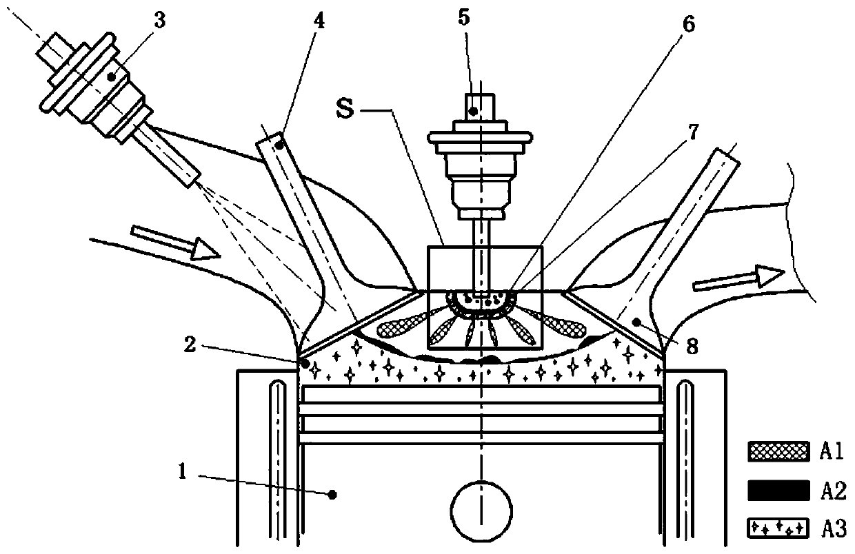
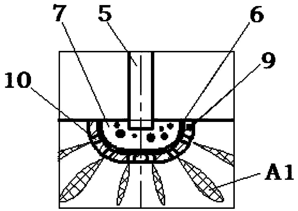
The invention relates to the technical field of gasoline engine combustion control methods, and particularly relates to a compression ignition jet ignition combustion system and a combustion control method. In the compression ignition jet ignition combustion system, a manifold oil injector and a direct injection oil injector jointly form a double-injection structure, and a sparking plug does not need to be arranged in the combustion system. An injection opening of the manifold oil injector of the combustion system is connected with an air inlet channel; and a jet chamber is arranged in a maincombustion chamber, an injection opening of the direct injection oil injector is connected with the jet chamber, and the jet chamber is used for enabling fuel oil injected by the direct injection oilinjector to be compressed and ignited to form compression ignition fuel gas and dispersing the compression ignition fuel gas into the main combustion chamber. According to the combustion system, on the basis of an existing engine, complex structure modification is not needed, cost is low, combustion stability is guaranteed, and robustness is high; and compared with a traditional flame jet combustion mode in the prior art, the combustion temperature is lower, nitrogen oxide emission in the engine is reduced, the burden of a lean-burn catalyst is relieved, and time-sharing and partition-controllable spontaneous combustion of the jet chamber and the main combustion chamber is achieved.

Description

technical field [0001] The invention relates to the technical field of gasoline engine combustion control methods, in particular to a compression ignition jet ignition combustion system and a combustion control method. Background technique [0002] Energy-saving and emission-reducing automotive engines have long been a theme. Gasoline engine is the main force of passenger car engine, and its high-efficiency and clean combustion to achieve extreme thermal efficiency has become a research hotspot in recent years. Under the technical background of the increasingly obvious trend of electrification, hybrid technology makes it possible to apply some new combustion methods in traditional gasoline engines in the environment of hybrid vehicles. Major car companies and related research institutes are actively developing hybrid gasoline engines. . [0003] With the assistance of the motor, the speed and load of the gasoline engine are decoupled from the vehicle speed and power demand...

Claims


Application Information

Patent Timeline
Patent Type & Authority Applications(China)
IPC IPC(8): F02B9/02F02D41/30F02M43/04F02M45/02
CPCF02B9/02F02D41/3094F02M43/04F02M45/02Y02T10/12
Inventor 王志范钦灏刘伟赵自庆
Owner TSINGHUA UNIV
Learn More