Surface mount inductor and method of manufacturing surface mount inductor
A technology of surface mounting and manufacturing method, which is used in the manufacture of inductors/transformers/magnets, inductors, fixed inductors, etc., which can solve the problems of reduced withstand voltage, small distance, and unstable adhesion between the molded body and the shielding component. , to achieve the effect of superior adhesion
- Summary
- Abstract
- Description
- Claims
- Application Information
AI Technical Summary
Problems solved by technology
Method used
Image

Examples
Embodiment 1
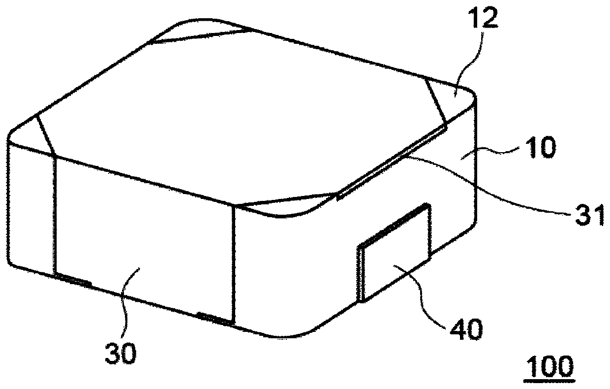
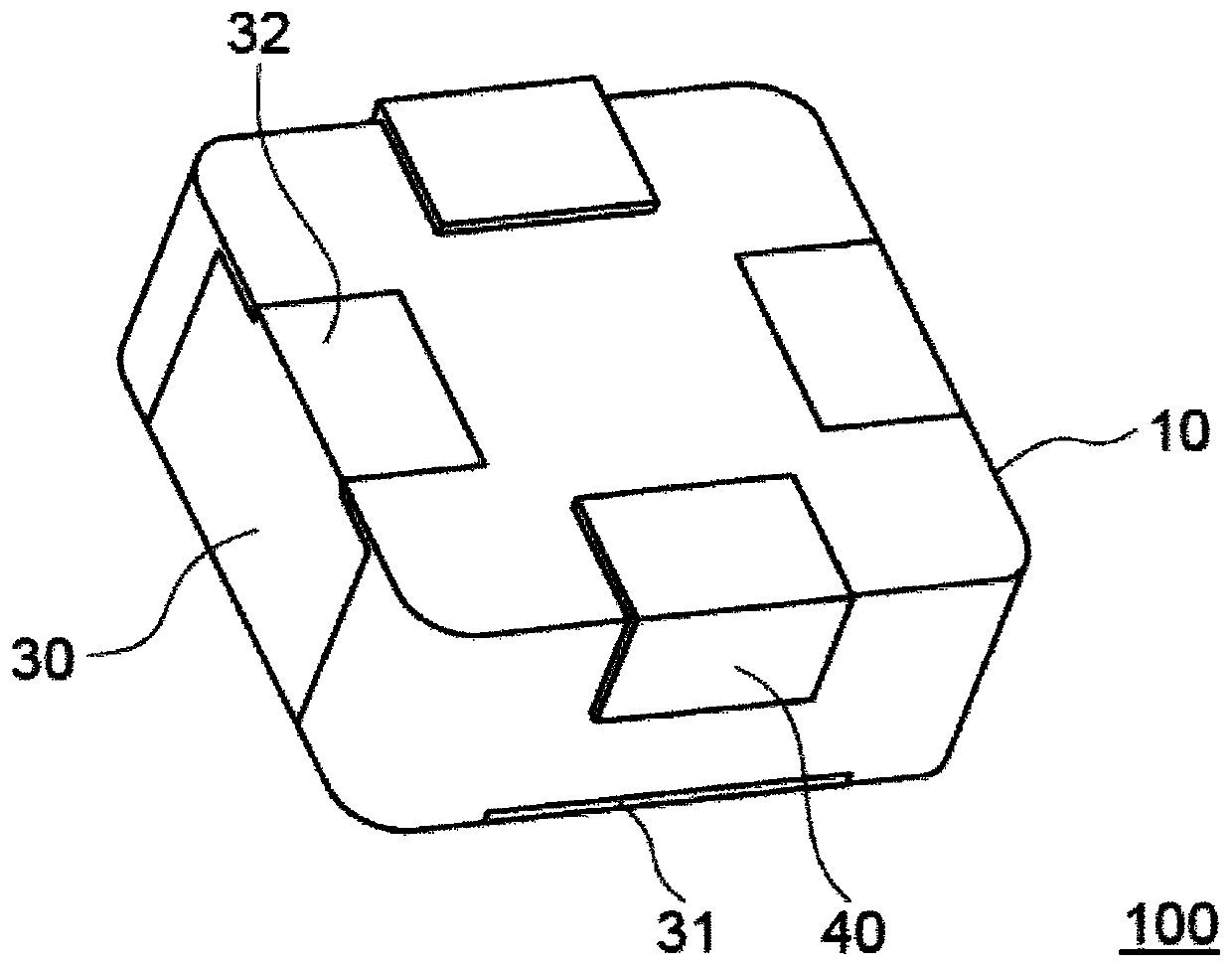
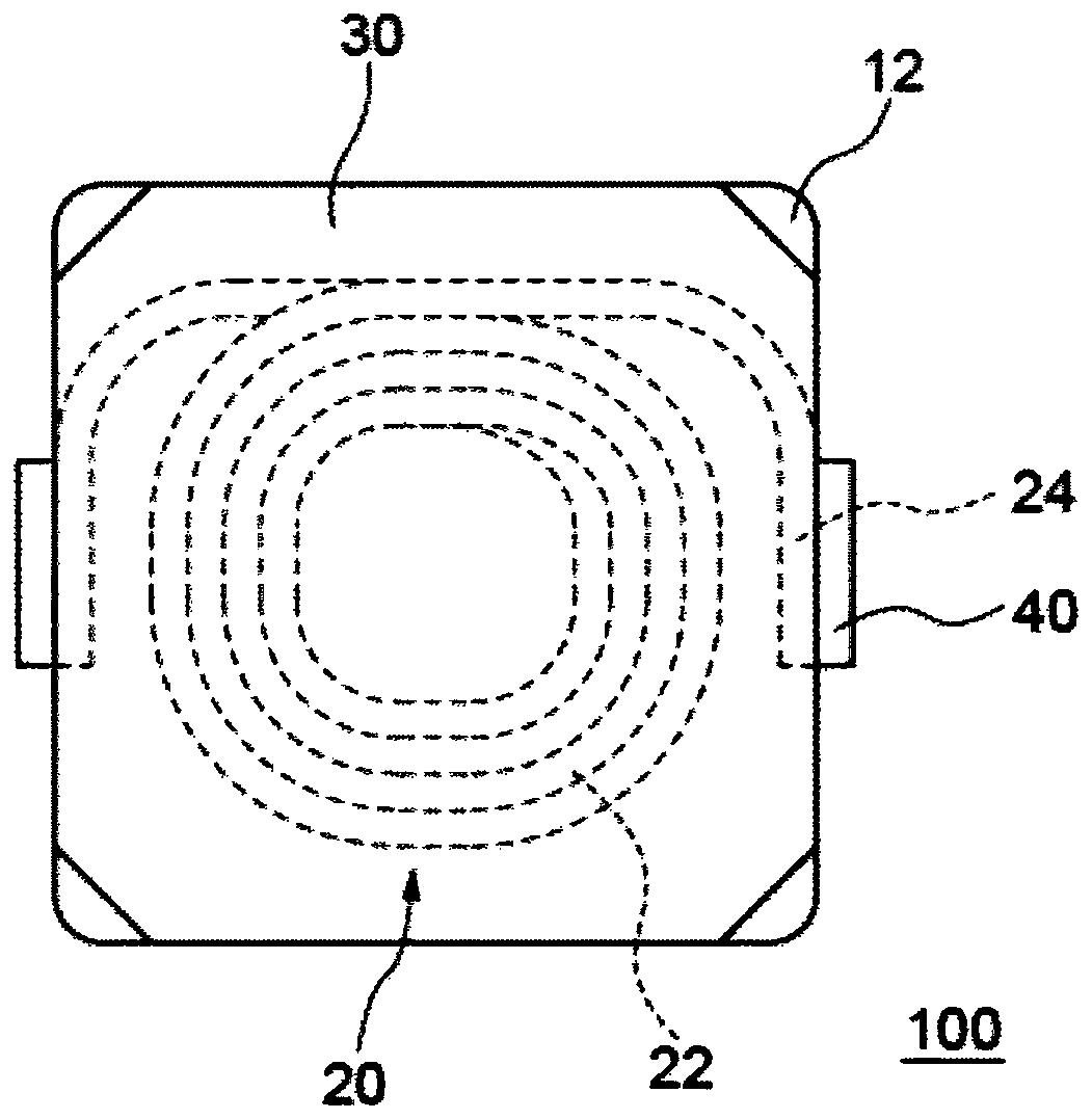
[0049] refer to Figure 1 to Figure 4 The surface mount inductor 100 of the first embodiment will be described. figure 1 is a schematic perspective view of the surface mount inductor 100 seen from the upper surface side opposite to the mounting surface side, figure 2 This is a schematic perspective view seen from the mounting surface side. image 3 It is a schematic partial perspective plan view seen from the upper surface side illustrating the internal structure of the surface mount inductor 100 . Figure 4 Among them, ( a1 ) to ( c2 ) are schematic plan views and schematic cross-sectional views for schematically explaining the manufacturing method of the surface mount inductor 100 .
[0050] Such as Figure 1 to Figure 3 As shown, the surface mount inductor 100 has: a molded body 10, which includes a composite material containing magnetic powder, and a coil is embedded; a pair of external terminals 40, which are electrically connected to the coil respectively; and a meta...
Embodiment 2
[0063] refer to Figure 5 The surface mount inductor 110 of the second embodiment will be described. Figure 5 It is a schematic perspective view of the surface mount inductor 110 seen from the upper surface side. In the surface mount inductor 110, the upper surface portion of the metal plate 30 arranged on the upper surface of the molded body 10 does not extend to the side surface on which the external terminal 40 is arranged, and the pair of side surfaces and the upper surface on which the metal plate 30 is arranged The surface mount inductor 110 has the same configuration as the surface mount inductor 100 of the first embodiment except that the continuous molded body exposed portion 12 is formed.
[0064] In the surface mount inductor 110 , the upper surface portion of the metal plate 30 has a width narrower than the width between the side surfaces of the molded body 10 on which the external terminals are disposed. In addition, the end surface of the metal plate 30 that f...
Embodiment 3
[0066] refer to Figure 6 to Figure 8 The surface mount inductor 120 of the third embodiment will be described. Figure 6 is a schematic partial perspective view seen from the upper surface side of the surface mount inductor 120, Figure 7 is through Figure 6 A schematic sectional view of a section taken along line A-A and perpendicular to the upper surface of the molded body. Figure 8 ( a1 ) to ( c2 ) are schematic plan views and schematic cross-sectional views schematically illustrating a method of manufacturing the surface mount inductor 120 . In the surface mount inductor 120, the upper surface part and the side part of the metal plate 30 are buried in the molded body 10, and the surface of the upper surface part and the side part of the metal plate 30 is not exposed from the molded body. In addition, the surface mount inductor 120 has the same configuration as the surface mount inductor 110 of the second embodiment.
[0067] Such as Figure 6 and Figure 7 As show...
PUM
| Property | Measurement | Unit |
|---|---|---|
| thickness | aaaaa | aaaaa |
Abstract
Description
Claims
Application Information
 - R&D
- Intellectual Property
- Life Sciences
- Materials
- Tech Scout
- Unparalleled Data Quality
- Higher Quality Content
- 60% Fewer Hallucinations
Browse by: Latest US Patents, China's latest patents, Technical Efficacy Thesaurus, Application Domain, Technology Topic, Popular Technical Reports.
© 2025 PatSnap. All rights reserved.Legal|Privacy policy|Modern Slavery Act Transparency Statement|Sitemap|About US| Contact US: help@patsnap.com