Permanent magnet synchronous motor static state rotor position identification method

A permanent magnet synchronous motor and rotor position technology, which is applied in the control of generators, motor control, motor generator control, etc., can solve the problems of small calculation amount of detection data, long time, small motor reversal angle, etc., and achieve start-up response High speed, low process noise, and improved reliability

Active Publication Date: 2020-03-27
RES INST OF ZHEJIANG UNIV TAIZHOU
View PDF6 Cites 0 Cited by
  • Summary
  • Abstract
  • Description
  • Claims
  • Application Information

AI Technical Summary

Problems solved by technology

[0005] The purpose of the present invention is to solve the problem that current high-frequency pulse injection method or pulse voltage injection detection current response method is used to identify the rotor position of permanent magnet synchronous motor in static state. Technical problem, to provide a permanent magnet synchronous motor static state rotor position identification method, by applying a small amplitude vector voltage to detect the current and phase voltage response, twice to detect the power factor value to conduct preliminary identification of the rotor angle, after the initial identification On the identified rotor angle position, the identified angle is verified again according to the power factor, and then the direct current closed-loop drives the motor to start, which has low requirements for current detection, does not need to detect the instantaneous pulse value of the response current, and the detection data calculation amount is small , lower requirements on the current sampling circuit and microcontroller, easy to reduce hardware costs, small-amplitude voltage drive to ensure rapid rotor position orientation during the detection process, short detection time, only need to wait for two times for the current to stabilize and converge, the motor feedback small turning angle

Method used


Image

  • Permanent magnet synchronous motor static state rotor position identification method
  • Permanent magnet synchronous motor static state rotor position identification method
  • Permanent magnet synchronous motor static state rotor position identification method

Examples


Embodiment Construction

[0017] The present invention will be preferably described below in conjunction with the accompanying drawings and specific embodiments.

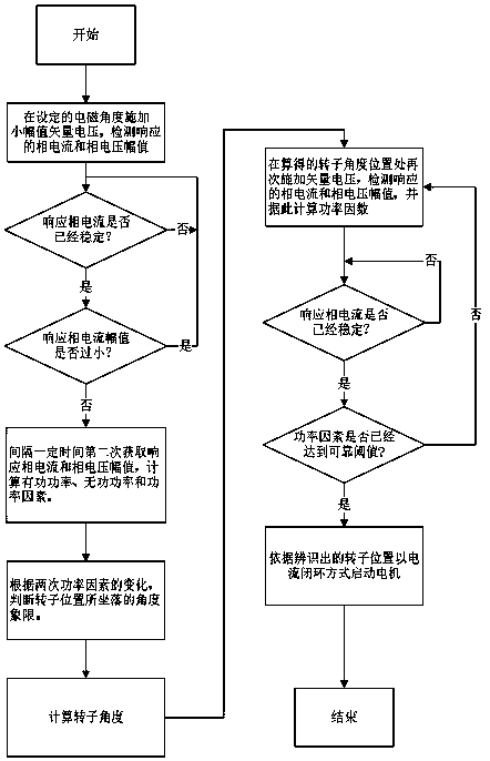
[0018] Such as figure 2 As shown, an embodiment of the rotor position identification method of the permanent magnet synchronous motor in the static state of the present invention includes the following steps:

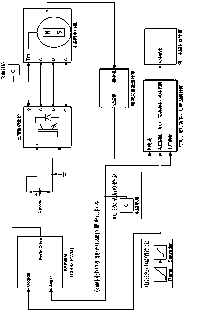
[0019] Step 1: applying a driving voltage with a small amplitude to the set electromagnetic angle. The electromagnetic angle is the parameters of each phase of the three-phase full-bridge driver (voltage, current, flux linkage, etc.), in the agreed motor analysis coordinate system (it is agreed that the U phase is used as the zero angle of the coordinate system, the V phase is located at 120 degrees, and the W phase is located at 240 degrees. degrees) and the angle between the resultant vector and the 0 degree angle. The amplitude of the small-amplitude driving voltage is set by the detection current and the motor line resistance, ...


PUM


Abstract

The invention discloses a permanent magnet synchronous motor static state rotor position identification method. The method comprises the following steps: (1) applying a small-amplitude driving voltageon a set electromagnetic angle; (2) detecting the amplitudes of the responded phase current and phase voltage, and detecting the amplitudes of the responded phase current and phase voltage for the second time at an interval of a certain time t; (3) respectively calculating active power, reactive power and a power factor according to the two detection values; (4) judging an angle quadrant where the rotor position is located according to the changes of the two power factors; and (5) calculating a rotor angle, applying the small-amplitude driving voltage again at the rotor angle, calculating a power factor according to the amplitudes of the responded phase current and phase voltage, and if the power factor reaches a reliable threshold, determining that the rotor angle is the rotor position in a static state. The requirement for current sampling is low, the pulse value at the moment of current response does not need to be detected, and the reliability of the detection result is improved.

Description

technical field [0001] The invention relates to a rotor position identification method in a static state of a permanent magnet synchronous motor. Background technique [0002] The drive method of the existing permanent magnet synchronous motor is usually the field oriented control, namely the vector control method. Vector control requires the identification of the position of the rotor poles. In the case of no position sensor, methods such as sliding mode observer, full-order observer and model reference self-adaptation are commonly used for position identification. The principle of these methods is to indirectly identify the rotor pole position by solving the back electromotive force when the motor rotates. The reverse electromotive force is very small at low speed of the motor, and the magnetic pole position is easily affected by sampling interference and cannot be converged, so it is difficult to apply to the motor starting from the initial static state. [0003] When t...

Claims


Application Information

Patent Timeline
Patent Type & Authority Applications(China)
IPC IPC(8): H02P21/34H02P21/32H02P21/18
CPCH02P2207/05H02P21/18H02P21/32H02P21/34
Inventor 王威颜建国赵瑜武建伟
Owner RES INST OF ZHEJIANG UNIV TAIZHOU
Why Eureka
Try Eureka