Complex structural part clamp

A technology of complex structure and fixture, applied in clamping, manufacturing tools, metal processing mechanical parts, etc., can solve the problems of unable to adapt to new technical requirements, unable to meet processing requirements, difficult to achieve rapid changeover, etc., to shorten the preparation time , The effect of shortening production preparation time and reducing the number of benchmark conversions

Inactive Publication Date: 2020-03-31
AECC AVIATION POWER CO LTD
View PDF6 Cites 0 Cited by
  • Summary
  • Abstract
  • Description
  • Claims
  • Application Information

AI Technical Summary

Problems solved by technology

When processing such structural parts, rough datums such as holes, surfaces, and outer circles are usually processed through scribing and roughing processes, and then the processed rough datums are used for positioning and clamping. The process is complicated and the processing efficiency is low. Multiple clamping and frequent benchmark changes during processing lead to poor quality stability
When clamping, a large number of fastening methods such as pressure plates and screws are used. The fixtures are complicated and difficult to

Method used


Image

  • Complex structural part clamp
  • Complex structural part clamp
  • Complex structural part clamp

Examples


Embodiment 1

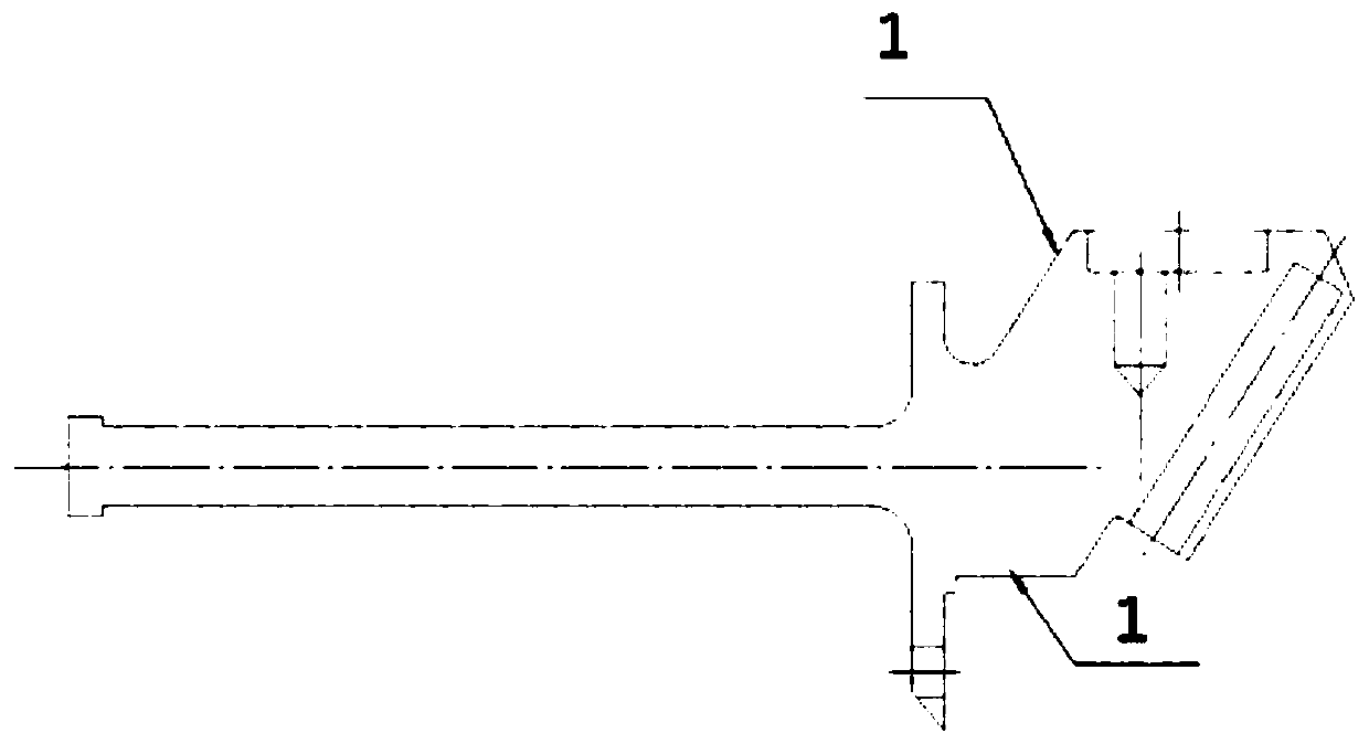
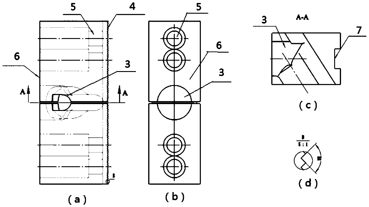
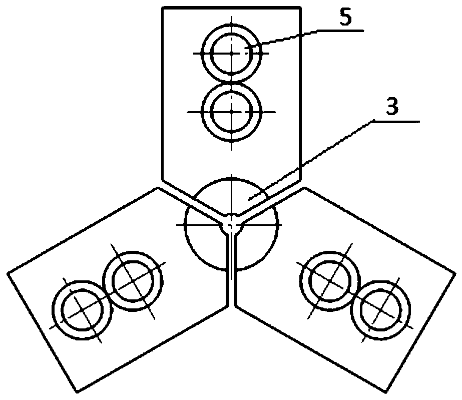
[0044] by figure 1 The aeroengine fuel nozzle housing is shown as an example, such as figure 2 As shown, the fixture in this embodiment includes two jaw units, and the profile of the clamping portion 3 of each jaw unit is consistent with figure 1 The outline of the middle nozzle shell fits, using figure 1 The middle positioning datum 1 is used for positioning, and the outline of the clamping part 3 is shown in Figure 2. When in use, the clamping parts 3 of the two claw units face each other to clamp the parts.

[0045] The fastening part of the jaw unit is a bolt hole 5, and the jaw unit is fastened on the machine tool through bolts.

[0046] The positioning part of the claw unit is a rack 4 structure and a keyway 7 structure, which is positioned by cooperating with the rack and chuck on the machine tool. The angle of rack 4 is 90 degrees.

[0047] The auxiliary measuring part of the claw unit is the auxiliary measuring surface 6. After the part is clamped, it is judged ...

Embodiment 2

[0049] Such as Figure 4 As shown, the claw unit structure in this embodiment is the same as that in Embodiment 1, except that there is no rack 4 structure, but two clamp positioning pins 8 are provided in the key groove 7 for positioning.

Embodiment 3

[0051] Such as Figure 5 As shown, the structure of the claw unit in this embodiment is the same as that in Embodiment 1, except that the claw unit in Embodiment 1 is a whole, while in this embodiment, the claw unit is a split structure, including a mating block 10 and a base 11. The clamping part 3, the fastening part and the auxiliary measuring part are arranged on the matching block 10, and the base 11 includes the positioning part and the fastening part. The mating block 10 is positioned and combined with the base 11 through the positioning pin 9 and the positioning surface 12 of the base block, and is fastened as a whole after the combination. The bolt hole 5 on the seat 11 is fixed on the machine tool.


PUM


Abstract

The invention provides a complex structural part clamp, which comprises a plurality of clamping jaw units. Each clamping jaw unit comprises a clamping part, a positioning part, a fastening part and anauxiliary measuring part. The outline of the clamping part is matched with the outline of a part, and the clamping parts of the multiple clamping jaw units are distributed in the circumferential direction to jointly clamp the part. The positioning part is used for positioning the clamping jaw unit and a machine tool; the fastening part is used for fastening the clamping jaw unit on the machine tool; and the auxiliary measurement part is used for verifying whether the clamping position of the part is reasonable. The current situations of poor quality stability and long production preparation time caused by repeated clamping and frequent benchmark conversion in the machining process of similar structural parts are improved, and the machining efficiency and the quality stability are improved.

Description

technical field [0001] The invention belongs to the field of quick-change tooling, in particular to a fixture for complex structural parts. Background technique [0002] Complex structural parts refer to structural parts that include planes, bosses, cavities, irregular shapes and other geometric features, with many spatial dimensions and complex configurations. When processing such structural parts, rough datums such as holes, surfaces, and outer circles are usually processed through scribing and roughing processes, and then the processed rough datums are used for positioning and clamping. The process is complicated and the processing efficiency is low. Multiple clamping and frequent benchmark changes during processing lead to poor quality stability. When clamping, a large number of fastening methods such as pressure plates and screws are used. The fixtures are complicated and difficult to achieve quick changeover, which is not conducive to automatic processing. With the w...

Claims


Application Information

Patent Timeline
IPC IPC(8): B23Q3/00
CPCB23Q3/00
Inventor 莫战海朱阳刘六九杨飞飞段瑞斐张亚军李洪岩梁磊
Owner AECC AVIATION POWER CO LTD
Why Eureka
Try Eureka