Composite lining structure of shield water delivery tunnel, and construction method for same

A technology of water conveyance tunnel and composite lining, applied in tunnel lining, wellbore lining, drainage, etc., can solve the problems of increased maintenance cost, unreasonable load sharing ratio, single structure of drainage system, etc., to improve durability and service life, Improve the stability of external pressure resistance and ensure the effect of pipeline water delivery efficiency

Pending Publication Date: 2020-03-31
SOUTH CHINA UNIV OF TECH
View PDF2 Cites 5 Cited by
  • Summary
  • Abstract
  • Description
  • Claims
  • Application Information

AI Technical Summary

Problems solved by technology

[0004] However, the existing water tunnel lining structure has the following defects: (1) The overall stiffness of the double-layer lining structure is too small, and the concrete lining structure is prone to serious cracking under high internal water pressure; (2) Although the three-layer lining structure is integral The rigidity is relatively high, but due to the unreasonable load sharing ratio, it will also lead to excessive load bearing of the concrete lining and the overall or partial cracking and damage; (3) The drainage system of the lining structure is single in structure, lacks systematicness, and has a high probability of blockage, which will cause The accumulation of water pressure will cause the steel lining to become concave and bulging and unstable; (4) the cracking and damage of the concrete lining will lead to an increase in maintenance costs during operation and reduce the durability and service life of the lining structure of the water conveyance tunnel

Method used


Image

  • Composite lining structure of shield water delivery tunnel, and construction method for same
  • Composite lining structure of shield water delivery tunnel, and construction method for same
  • Composite lining structure of shield water delivery tunnel, and construction method for same

Examples


Embodiment Construction

[0034] The purpose of the present invention will be further described in detail through specific examples below, and the examples cannot be repeated here one by one, but the implementation of the present invention is not therefore limited to the following examples.

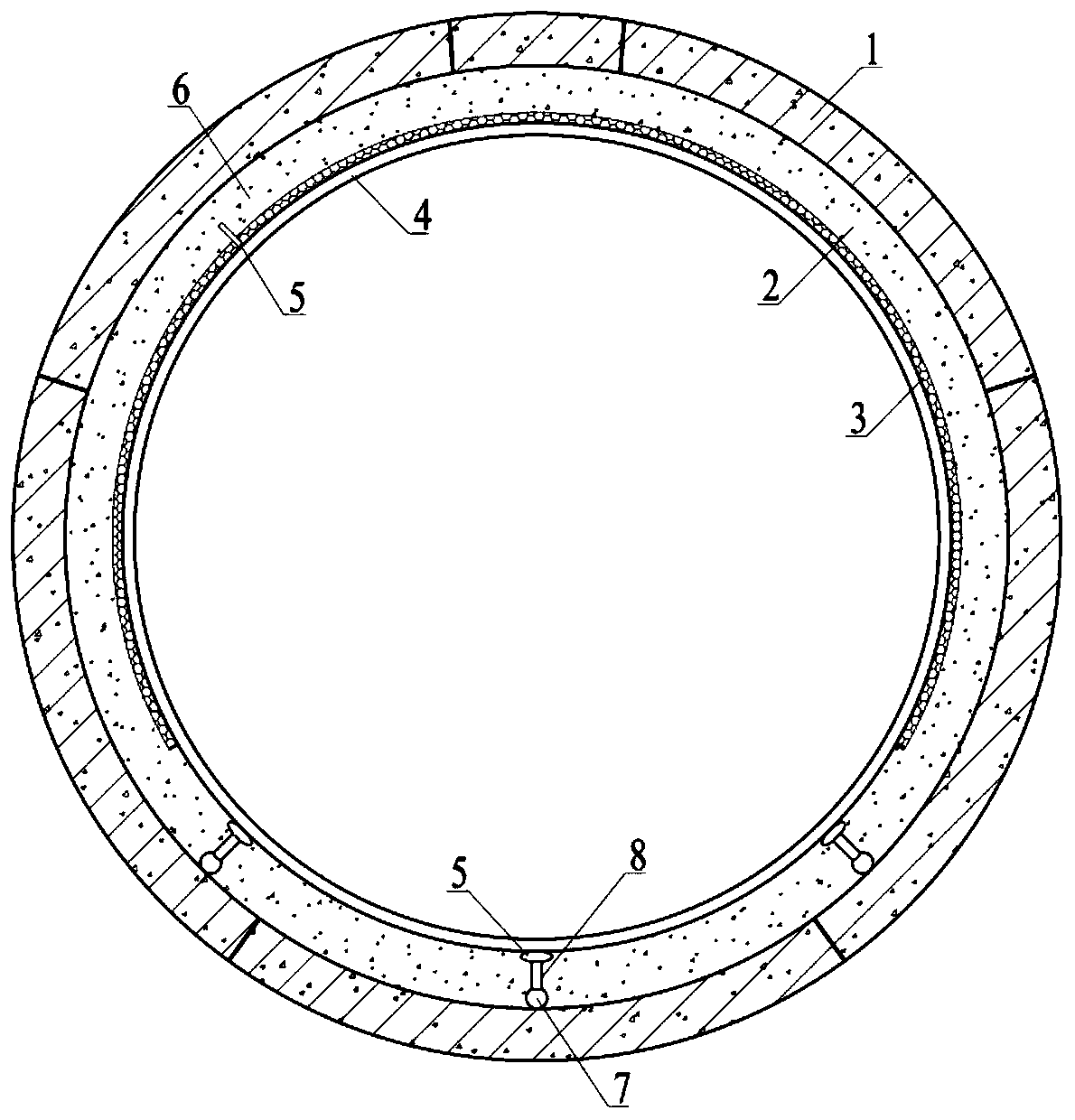
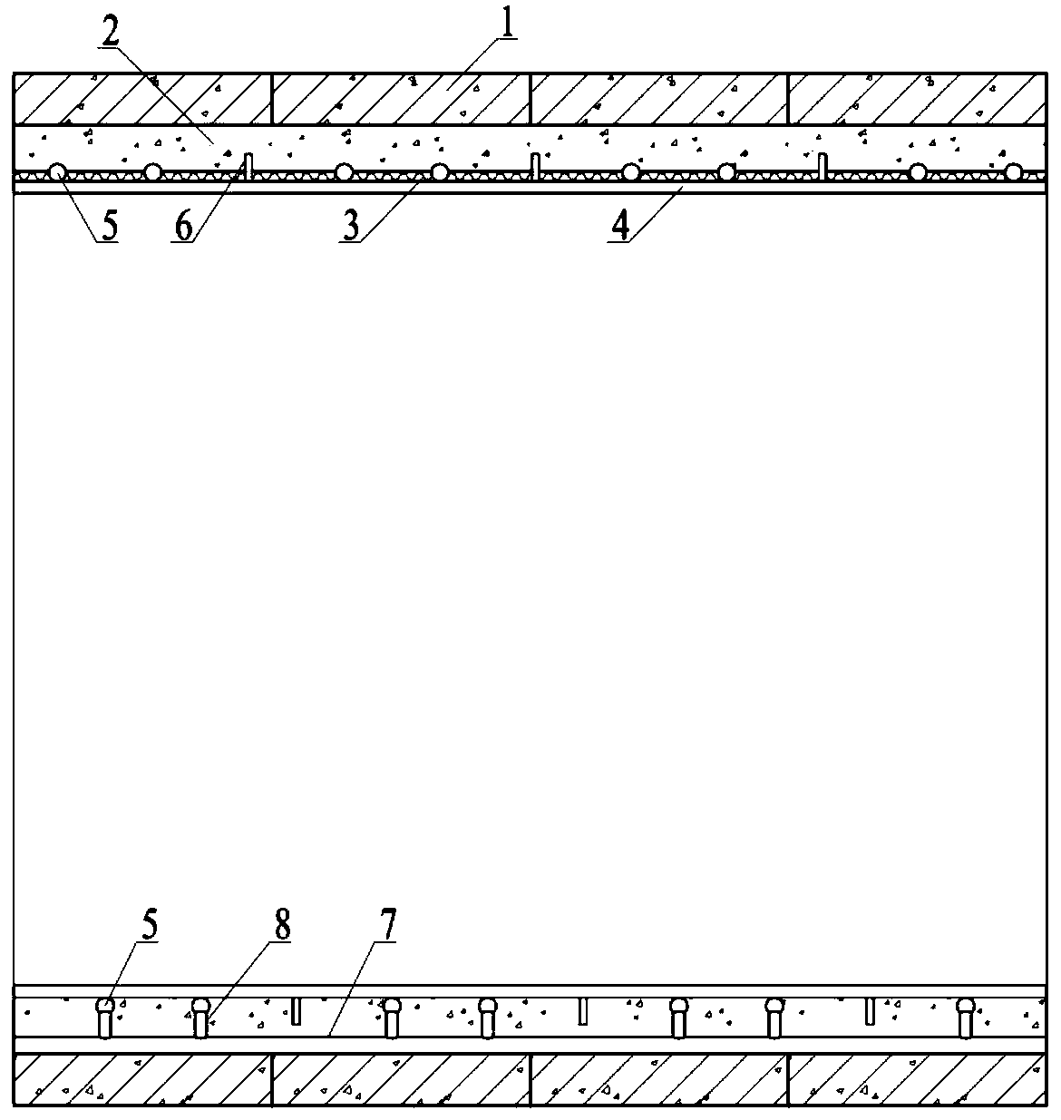
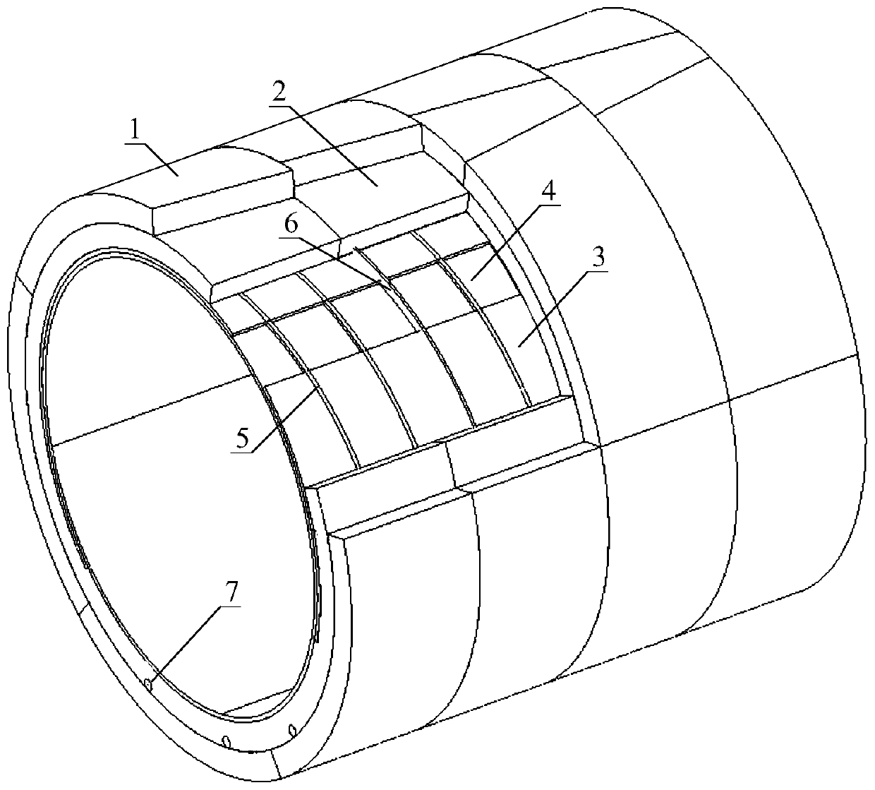
[0035] As shown in the accompanying drawings, a composite lining structure of a shield water conveyance tunnel includes an outermost shield tunnel segment 1, an inner steel lining 4, the steel lining 4 is cylindrical, and the steel lining 4 The outer surface of the steel lining 4 is welded with a stiffening ring 6, the outer surface of the steel lining 4 is provided with a flexible liner 3 at 240° to 300°, the outer surface of the steel lining is provided with a drainage flower tube 5, and the shield tunnel segment 1 is provided with a longitudinal drainage pipe 7 at the inner bottom, the drainage flower pipe 5 communicates with the longitudinal drainage pipe 7 through a connecting conduit 8, and concrete is filled...


PUM


Abstract

The invention discloses a composite lining structure of a shield water delivery tunnel, and a construction method for the same. The composite lining structure of the water delivery tunnel comprises ashield tunnel pipe sheet on an outmost layer and a steel lining on an inner layer, wherein the steel lining is cylindrical; and a reinforcement ring is welded on the outer surface of the steel lining.The composite lining structure is characterized in that a flexible liner is disposed at a degree of 240 DEG-300 DEG on the outer surface of the steel lining; a drainage floral tube is disposed on theouter surface of the steel lining; a longitudinal drainage pipe is disposed on the bottom of the inner side of the shield tunnel pipe sheet; the drainage floral tube communicates with the longitudinal drainage tube by a connecting conduit; and a concrete filling layer is filled between the shield tunnel pipe sheet and the steel lining and between the shield tunnel pipe sheet and the flexible liner. The composite lining structure disclosed by the invention has the beneficial effects that bearing proportions of tubes on different composite lining layers can be allocated rationally; a bearing advantage of tube materials can be exerted; a possibility in cracking and breaking of the concrete filling layer and the shield tunnel pipe sheet is reduced; and with a systematic meshed drainage system, inward sinking and swelling on pipe walls of the steel lining caused by accumulation of external water pressures can be avoided, and pipeline water delivery efficiency is ensured.

Description

technical field [0001] The invention relates to the technical field of tunnel engineering, in particular to a composite lining structure of a water delivery tunnel and a construction method thereof. Background technique [0002] Shield water conveyance tunnel is an underground structure system constructed in rock (soil) by shield method, and it is an important part of underground water conveyance project. Especially when the water conveyance tunnel is buried deep underground, the water conveyance tunnel faces unfavorable conditions such as high internal and external water pressure, high surrounding rock pressure, and complex stratum conditions. At present, multi-layer lining is often used. There are three main problems faced. First, the outer concrete lining cracks under the high internal water pressure of the water conveyance tunnel lining structure, which will lead to the overall degradation of the bearing performance of the lining structure; second, after the concrete lin...

Claims


Application Information

Patent Timeline
Patent Type & Authority Applications(China)
IPC IPC(8): E21D11/08E21D11/18E21D11/05E21D11/10E21F16/02
CPCE21D11/05E21D11/08E21D11/10E21D11/105E21D11/18E21F16/02
Inventor 刘庭金唐永锋杨小平廖强林少群
Owner SOUTH CHINA UNIV OF TECH
Why Eureka
Try Eureka