
Multi-load wireless power transmission system with constant power and constant efficiency characteristics

A technology with efficiency characteristics and wireless power transmission, applied in electrical components, circuit devices, etc., can solve the problems of low spatial freedom, excessive system volume, and small radial offset range, so as to improve the spatial freedom and system robustness. Strong and practical effect

Pending Publication Date: 2020-03-31
SOUTH CHINA UNIV OF TECH
View PDF0 Cites 11 Cited by
  • Summary
  • Abstract
  • Description
  • Claims
  • Application Information

AI Technical Summary

Problems solved by technology

However, the existing single-input multiple-output multi-load wireless power transmission systems all adopt the principle of inductive or resonant wireless power transmission. When the load position or direction changes, the output power and transmission efficiency of each load will change significantly, and the constant power cannot be maintained. , Constant efficiency output, short axial movement distance of the load, small radial offset range, and low spatial freedom
In order to improve the degree of spatial freedom, the existing technology often adopts increasing the area of ​​the transmitting coil, adopting a three-dimensional transmitting coil or adding an additional compensation circuit, but at the same time it brings problems such as excessive system volume, increased cost, complicated control, and reduced reliability.

Method used


Image

  • Multi-load wireless power transmission system with constant power and constant efficiency characteristics
  • Multi-load wireless power transmission system with constant power and constant efficiency characteristics
  • Multi-load wireless power transmission system with constant power and constant efficiency characteristics

Examples


Embodiment Construction

[0025] The present invention will be further described below in conjunction with specific examples.

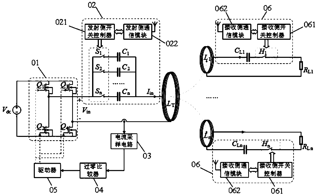
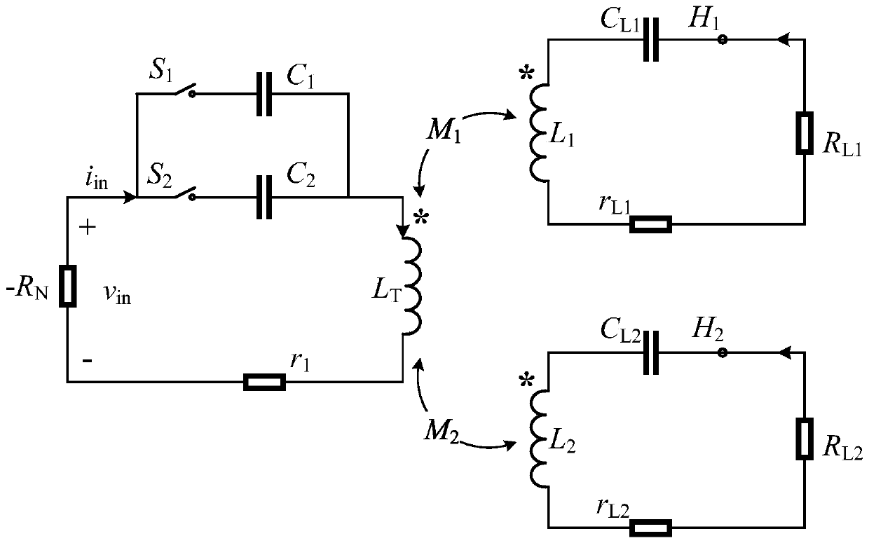
[0026] Such as figure 1 As shown, the multi-load wireless power transmission system with constant power and constant efficiency characteristics provided by this embodiment includes a transmitting device and at least two receiving devices; the transmitting device is connected in sequence by a DC power supply V dc , full bridge inverter 01, transmitting side resonant capacitor module 02, transmitting coil L T , a current sampling circuit 03, a zero-crossing comparator 04, and a driver 05, the driver 05 is connected to the full-bridge inverter 01, wherein the transmitting-side resonant capacitor module includes a transmitting-side switch controller 021, a transmitting-side communication module 022 and at least two parallel switched capacitor branches, the number of the switched capacitor branches is consistent with the number of receiving devices, and each switched capacitor bra...


PUM


Abstract

The invention discloses a multi-load wireless power transmission system with constant power and constant efficiency characteristics. The multi-load wireless power transmission system comprises a transmitting device and at least two receiving devices, the transmitting device is composed of a direct-current power supply, a full-bridge inverter, a transmitting side resonant capacitor module, a transmitting coil, a current sampling circuit, a zero-crossing comparator and a driver which are connected in sequence. The transmitting side resonant capacitor module comprises a transmitting side switch controller, a transmitting side communication module and at least two parallel switched capacitor branches, and each switched capacitor branch is formed by connecting a transmitting side switch and a transmitting side resonant capacitor in series; each receiving device is composed of a receiving coil, a receiving side resonance capacitor module and a load which are connected in series, and the receiving side resonance capacitor module comprises a receiving side resonance capacitor, a receiving side switch, a receiving side switch controller and a receiving side communication module which are connected in sequence. The method has the characteristics of constant power and constant efficiency, high system spatial freedom degree, high robustness, simple circuit structure and easiness in implementation.

Description

technical field [0001] The invention relates to the technical field of wireless power transmission, in particular to a multi-load wireless power transmission system with constant power and constant efficiency characteristics. Background technique [0002] Wireless power transmission technology directly transmits power to the load through the air without wires or other physical connections, and has the advantages of flexible and convenient power transmission. It is widely used in portable electronic devices, household appliances, electric vehicles, and implanted medical power supplies. For a long time, the power supply object of the wireless power transmission system is mostly a single load, and only "point-to-point" wireless power transmission can be performed. The system utilization rate is low, the space degree of freedom is low, and the system transmission performance is sensitive to the change of the load position. With the increasing number of electrical and electronic ...

Claims


Application Information

Patent Timeline
IPC IPC(8): H02J50/12H02J50/40
CPCH02J50/12H02J50/40
Inventor 丘东元罗成鑫张波林满豪肖文勋
Owner SOUTH CHINA UNIV OF TECH
Learn More