Two-stage heat exchange type cyclone separator

A cyclone separator and heat exchange technology, which is applied in the direction of swirl devices and devices whose axial direction can be reversed, can solve the problems of wasting waste heat of flue gas, realize the recovery and utilization of waste heat, and improve the separation efficiency Effect

Inactive Publication Date: 2020-04-03
SHANDONG UNIV OF SCI & TECH
View PDF8 Cites 0 Cited by
  • Summary
  • Abstract
  • Description
  • Claims
  • Application Information

AI Technical Summary

Problems solved by technology

However, the waste heat carried by the industrial flue gas is directly discharged into the atmosphere after passing through the cyclone separator, which wastes a lot of waste heat of the flue gas.

Method used


Image

  • Two-stage heat exchange type cyclone separator
  • Two-stage heat exchange type cyclone separator
  • Two-stage heat exchange type cyclone separator

Examples


Embodiment Construction

[0014] The present invention will be further explained below in conjunction with the accompanying drawings.

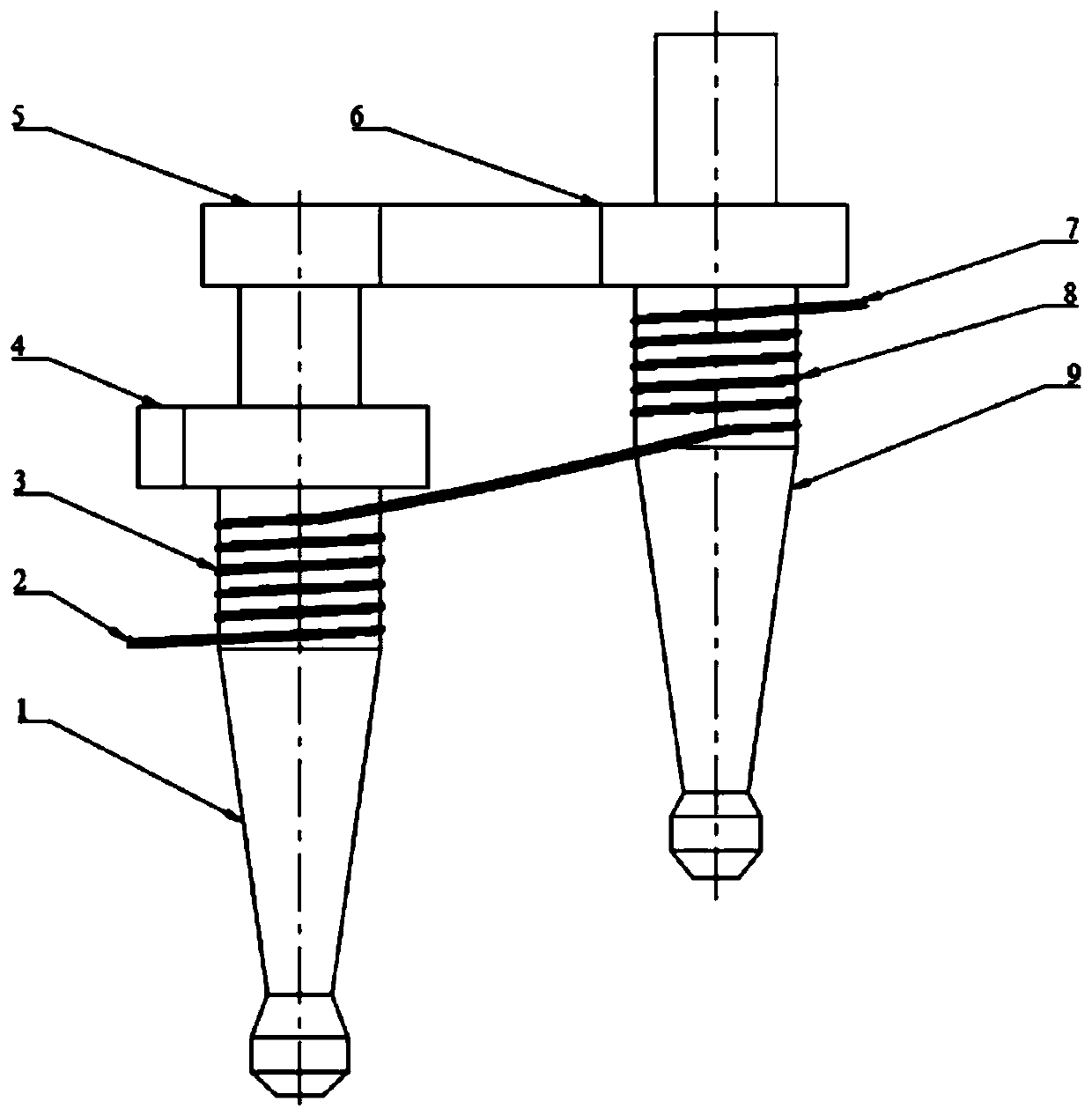
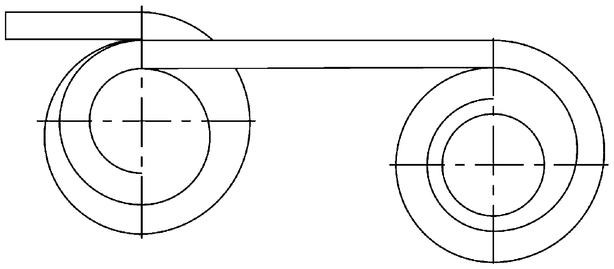
[0015] Such as figure 1 , figure 2 Shown, a kind of two-stage heat exchange type cyclone separator comprises a primary cyclone separator 1 and a secondary cyclone separator 9, the air inlet 4 of the primary cyclone separator 1 and the intake air of the secondary cyclone separator 9 The ports 6 are all 360° volute type air inlets arranged on the top of the side wall of the wind separator, and the exhaust port on the top of the primary cyclone separator 1 passes through the inlet of the 180° volute type pipeline 5 and the secondary cyclone separator 9. Air port 6 is connected.

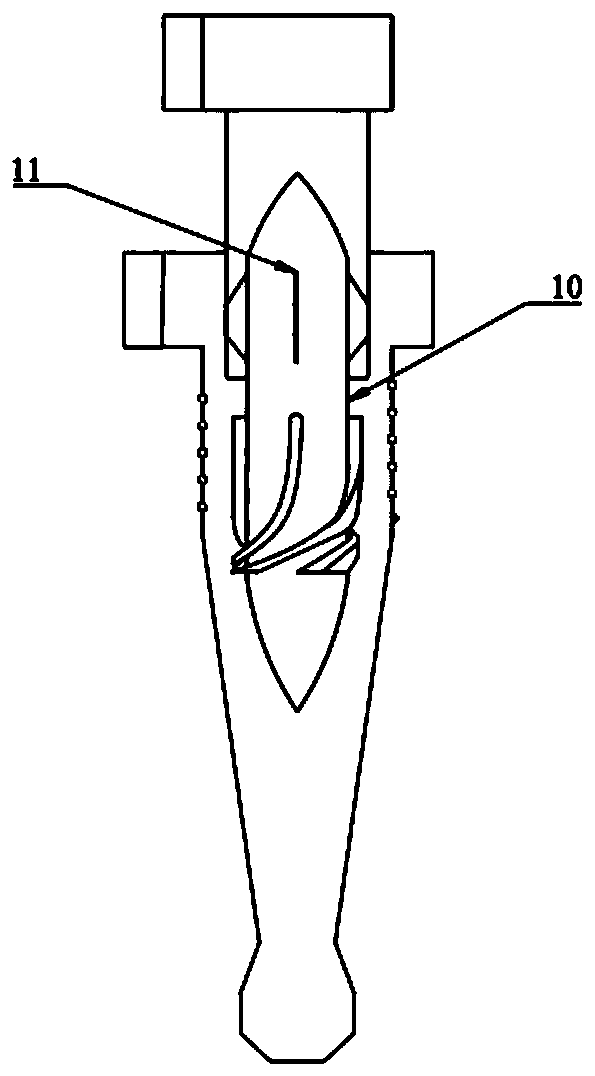
[0016] Such as Figure 4 As shown, the shells of the primary cyclone separator 1 and the secondary cyclone separator 9 both include an upper straight section and a lower conical section, and the outer wall of the straight section is provided with a spiral groove. The outer wall of the first-...


PUM


Abstract

The invention discloses a two-stage heat exchange type cyclone separator, which has the functions of heat exchange and dust removal at the same time, and a first-stage cyclone separator and a second-stage cyclone separator are selected, wherein fluid directors are arranged in cylindrical sections of the first-stage cyclone separator and the second-stage cyclone separator; the first-stage cyclone separator and the second-stage cyclone separator adopt 360-degree volute type air inlets; and an exhaust port of the first-stage cyclone separator is communicated with an air inlet of the second-stagecyclone separator through a 180-degree volute type pipeline. Heat exchange pipes are coiled on the outer walls of the cylindrical sections of the first-stage cyclone separator and the second-stage cyclone separator, and the rotating direction of the heat exchange pipes is opposite to the airflow direction of the cyclone separators. The cyclone separator not only can improve the separation efficiency and reduce the pressure drop, but also can utilize the waste heat and reduce the energy consumption.

Description

technical field [0001] The invention belongs to the field of dust removal and heat exchange, and in particular relates to a two-stage cyclone separator capable of utilizing waste heat. Background technique [0002] The cyclone separator uses the centrifugal force generated by the high-speed rotating movement of the dust-laden airflow inside to separate the dust particles from the airflow and trap them on the wall of the device, and finally fall into the ash hopper under the action of gravity, so as to achieve the purpose of dust removal Dry gas-solid separation equipment. Due to the advantages of high dust removal efficiency, simple structure, low cost, convenient operation and high reliability, this kind of separation and dust removal equipment is widely used in iron and steel metallurgy, chemical industry, thermal power generation and other industrial fields. In recent years, environmental problems have become increasingly prominent, especially smoke and dust pollution ca...

Claims


Application Information

Patent Timeline
Patent Type & Authority Applications(China)
IPC IPC(8): B04C5/26B04C5/20
CPCB04C5/26B04C5/20
Inventor 戚美王伯韬路成刘磊
Owner SHANDONG UNIV OF SCI & TECH
Why Eureka
Try Eureka