Inorganic mixture high-speed stirring mechanism and application method thereof

A technology of high-speed mixing and application method, applied in cement mixing devices, chemical instruments and methods, and raw material supply devices for sales, etc. problems, to achieve the effect of shortening length, proportion and time, small footprint and simple structure

Pending Publication Date: 2020-04-03
SHAANXI ZHONGDA LIDING TECH CO LTD
View PDF0 Cites 0 Cited by
  • Summary
  • Abstract
  • Description
  • Claims
  • Application Information

AI Technical Summary

Problems solved by technology

[0002] Stabilized soil mixing station is a general term for large-scale machinery used in civil engineering mixing construction in industrial construction. It is mainly used for base stabilized soil and concrete construction of high-grade highways, urban roads, squares, airports and other facilities. The current construction standards require stabilized soil The mixing equipment should adopt the two-time mixing production process, that is, two mixing tanks are used in series, so that the mixing time is not less than 15 seconds. The original intention of this standard is that the length of a single mixing tank is limited, and the mixing time is difficult to ensure mixing. uniformity of mixing
[0003] However, the use of two mixing tanks in series will undoubtedly double the power consumption of the mixing tank; at the same time, due to the original equipment configuration and site constraints of some mixing stations, it is not easy to connect two mixing tanks in series, and thus cannot meet the requirements Current Construction Standards Bring New Problems to Stabilized Soil Mixing

Method used


Image

  • Inorganic mixture high-speed stirring mechanism and application method thereof
  • Inorganic mixture high-speed stirring mechanism and application method thereof
  • Inorganic mixture high-speed stirring mechanism and application method thereof

Examples


no. 1 approach

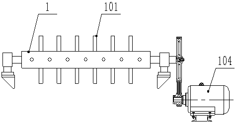
[0041] refer to figure 1 , the first embodiment of the present invention relates to a high-speed mixing mechanism for inorganic mixtures, including a material channel for breaking materials that can be arranged on the material passage between the material outlet 301 of the material conveyor 3 and the material inlet of the mixing tank 2. A high-speed stirring shaft 1 with graded stratification. Several stirring bodies 101 for turning and stirring materials are installed on the shaft wall of the high-speed stirring shaft 1. The stirring bodies 101 are in the shape of rods, blades, or picks. , any combination of two or three;

[0042] The rotating speed of the high-speed stirring shaft 1 is greater than the speed of the free-falling material output from the material conveyor 3 ; the input end of the high-speed stirring shaft 1 is connected to the driving device 104 .

[0043] The working process of the high-speed mixing mechanism for inorganic mixture is as follows:

[0044] li...

no. 2 approach

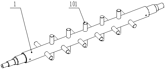
[0056] The difference between this embodiment and the first embodiment is that, referring to figure 2 , the stirring body 101 is rod-shaped, and the rod-shaped stirring body 101 vertically runs through the high-speed stirring shaft 1 and is symmetrically distributed on both sides of the high-speed stirring shaft 1. The adjacent stirring bodies 101 form an included angle with each other, and all the stirring bodies 101 are evenly spaced arranged.

[0057] The rod-shaped stirring body 101 is mainly suitable for small and medium-sized equipment and finely crushed materials, such as gravel. The arrangement of the rod-shaped stirring body 101 on the shaft wall of the high-speed stirring shaft 1 is not limited to figure 2 As shown, other arrangements are also possible, such as forming an angle other than a right angle to each other.

no. 3 approach

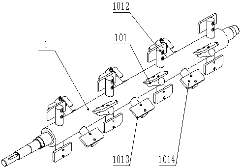
[0059] The difference between this embodiment and the first embodiment is that, referring to image 3 , the stirring body 101 is blade-shaped, and several blade-shaped stirring bodies 101 are uniformly distributed on the shaft wall of the high-speed stirring shaft 1, and two adjacent blade-shaped stirring bodies 101 are staggered to form an included angle, and each blade-shaped The stirring body 101 includes a supporting column 1012 vertically penetrating the high-speed stirring shaft 1. The part of the supporting column 1012 extending out of the high-speed stirring shaft 1 has the same length. 1013, the guide vane 1013 has two parallel and opposite planes, one of which is fixed to the column wall of the support column 1012, and the other plane is away from the column wall of the support column 1012, this plane is the stirring surface 1014, the same support column 1012 The stirring surfaces 1014 of the guide vanes 1013 at both ends are away from each other.

[0060] When mixi...


PUM


Abstract

The invention protects an inorganic mixture high-speed stirring mechanism. The inorganic mixture high-speed stirring mechanism comprises a high-speed stirring shaft which can be arranged on a materialchannel between a material conveyor and a stirring cylinder and is used for breaking material gradation layering, a stirring body is arranged on the shaft wall of the high-speed stirring shaft, and the stirring body is of a rod shape, a blade shape or a cutting tooth shape. According to the inorganic mixture high-speed stirring mechanism, materials conveyed by the material conveyor firstly fall into the high-speed stirring shaft, are overturned and stirred at a high speed and then enter the stirring cylinder, so that on one hand, the gradation layering of the materials and the agglomeration characteristic of mixtures are quickly broken, and on the other hand, the materials are forcibly mixed and then enter the stirring cylinder, the length specific gravity of a gathering and mixing low-efficiency area occupied by the materials of all levels in the stirring cylinder and the mixing time of the gathering and mixing low-efficiency area are reduced, the length specific gravity and time ofa medium-efficiency area and a high-efficiency area are relatively prolonged, and the mixing effect and quality are improved.

Description

technical field [0001] The invention belongs to the field of mixing and stirring equipment, and in particular relates to a high-speed stirring mechanism for an inorganic mixture and an application method thereof. Background technique [0002] Stabilized soil mixing station is a general term for large-scale machinery used in civil engineering mixing construction in industrial construction. It is mainly used for base stabilized soil and concrete construction of high-grade highways, urban roads, squares, airports and other facilities. The current construction standards require stabilized soil The mixing equipment should adopt the two-time mixing production process, that is, two mixing tanks are used in series, so that the mixing time is not less than 15 seconds. The original intention of this standard is that the length of a single mixing tank is limited, and the mixing time is difficult to ensure mixing. The mixing uniformity of the material. [0003] However, the use of two ...

Claims


Application Information

Patent Timeline
Patent Type & Authority Applications(China)
IPC IPC(8): B28C5/08B28C7/06B28C5/14B28C7/12
CPCB28C5/0806B28C5/142B28C5/148B28C7/06B28C7/128
Inventor 綦开隆武鸿孙雪妮
Owner SHAANXI ZHONGDA LIDING TECH CO LTD
Why Eureka
Try Eureka