Inorganic mixture high-speed stirring device and stirring method

A high-speed mixing and mixing technology, which is applied to cement mixing devices, chemical instruments and methods, and sales of raw material supply devices, etc., can solve the problems of inability to connect mixing tanks in series, high power consumption, etc., and achieve small footprint, easy implementation, The effect of low investment

Pending Publication Date: 2020-04-10
SHAANXI ZHONGDA LIDING TECH CO LTD
View PDF0 Cites 1 Cited by
  • Summary
  • Abstract
  • Description
  • Claims
  • Application Information

AI Technical Summary

Problems solved by technology

[0004] The embodiment of the present invention provides a high-speed mixing device and mixing method for inorganic mixtures. The first purpose is to solve the problem of large power consumption caused by connecting two mixing tanks in series; the second purpose is to solve the problem of the original equipment of the mixing station Configuration and site restrictions, the problem that two mixing tanks cannot be connected in series

Method used


Image

  • Inorganic mixture high-speed stirring device and stirring method
  • Inorganic mixture high-speed stirring device and stirring method
  • Inorganic mixture high-speed stirring device and stirring method

Examples


no. 1 approach

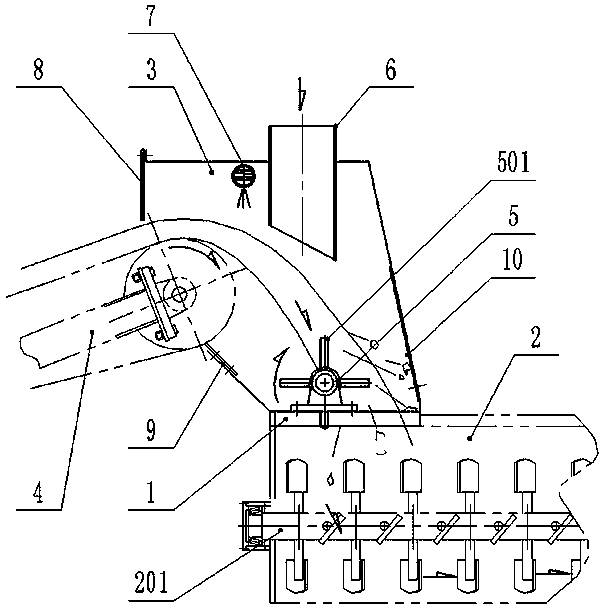
[0034] refer to figure 1 and figure 2 , the first embodiment of the present invention relates to a high-speed mixing device for inorganic mixtures, including a frame 1, a mixing tank 2 below the frame 1, a machine cover 3 above the frame 1, and the side wall of the machine cover 3 is sealed Connect the material conveyor 4, the discharge end of the material conveyor 4 extends into the hood 3, and also includes a high-speed stirring shaft 5 located in the hood 3, the high-speed stirring shaft 5 is located directly below the discharge end of the material conveyor 4 and Between the mixing tanks 2, the material output from the discharge end of the material conveyor 4 first passes through the high-speed mixing shaft 5 and then falls into the mixing tank 2. The input and output ends of the high-speed mixing shaft 5 are respectively fixed to the frame 1 through bearing seats. , the input end extends out of the machine cover 3 and is externally connected to the driving device 11; the...

no. 2 approach

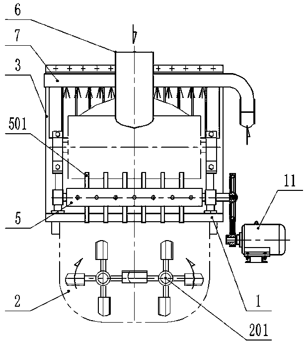
[0046] This embodiment relates to a high-speed stirring device for inorganic mixture, such as figure 1 and figure 2 As shown, including the frame 1, the bottom of the frame 1 is the mixing tank 2, the top of the frame 1 is the hood 3, the side wall of the hood 3 is sealed and connected to the material conveyor 4, and the discharge end of the material conveyor 4 extends Into the machine cover 3, it also includes a high-speed stirring shaft 5 arranged in the machine cover 3. The high-speed stirring shaft 5 is located between the mixing cylinder 2 directly below the discharge end of the material conveyor 4, and is output from the discharge end of the material conveyor 4. The material first passes through the high-speed stirring shaft 5 and then falls into the mixing tank 2. The input end and output end of the high-speed stirring shaft 5 are fixedly connected to the frame 1 through the bearing seat respectively, and the input end extends out of the machine cover 3 and is external...

no. 3 approach

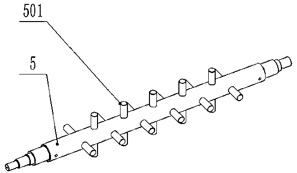
[0050] On the basis of the second embodiment, refer to image 3 , the stirring body 501 is rod-shaped, and the rod-shaped stirring body 501 vertically runs through the high-speed stirring shaft 5 and is symmetrically distributed on both sides of the high-speed stirring shaft 5. The adjacent stirring bodies 501 form an included angle (such as being perpendicular to each other, forming 60° each other) etc.), and all the stirring bodies 501 are evenly spaced.

[0051] The rod-shaped stirring body 501 is mainly suitable for small and medium-sized equipment and finely crushed materials, such as gravel. The arrangement of the rod-shaped stirring body 501 on the shaft wall of the high-speed stirring shaft 5 is not limited to image 3 As shown, other arrangements are also possible, such as forming an angle other than a right angle to each other.


PUM


Abstract

The invention discloses an inorganic mixture high-speed stirring device and stirring method. The device comprises a rack and a high-speed stirring shaft, wherein a stirring tank is arranged under therack; a machine cover is arranged above the rack and is connected with a material conveyor; materials conveyed from the material conveyor fall into the stirring tank; the high-speed stirring shaft islocated between the right below part of the discharge end of the material conveyor and the stirring tank; and a plurality of stirring bodies are arranged on the shaft wall of the high-speed stirring shaft. The materials conveyed from the material conveyor firstly fall into the high-speed stirring shaft so as to be stirred and then enter the stirring tank, so that on one hand, the graded layering of the materials and agglomeration characteristics of binders are broken; and on the other hand, the materials are firstly forced to be mixed and then enter the stirring tank, the inefficient zone length of aggregation and mixing and the mixing time occupied by the materials at different levels in the stirring tank are reduced, the relatively uniform and uniform high efficiency zone lengths and mixing time are prolonged, especially the inefficient zone mixing section length proportion and the time occupied by inorganic binders or powder in the stirring tank are shortened, and a mixing effect and the quality are improved.

Description

technical field [0001] The invention belongs to the technical field of mixing and stirring, and in particular relates to a high-speed stirring device and a stirring method for an inorganic mixture. Background technique [0002] Stabilized soil mixing station is a general term for large-scale machinery used in civil engineering mixing construction in industrial construction. It is mainly used for base stabilized soil and concrete construction of high-grade highways, urban roads, squares, airports and other facilities. The current construction standards require stabilized soil The mixing equipment should adopt the two-time mixing production process, that is, two mixing tanks are used in series, so that the mixing time is not less than 15 seconds. The original intention of this standard is that the length of a single mixing tank is limited, and the mixing time is difficult to ensure mixing. The mixing uniformity of the material. [0003] However, the use of two mixing tanks in...

Claims


Application Information

Patent Timeline
Patent Type & Authority Applications(China)
IPC IPC(8): B28C5/08B28C7/06B28C5/14B28C7/12
CPCB28C5/0806B28C5/142B28C5/148B28C7/06B28C7/128
Inventor 綦开隆武鸿李伟
Owner SHAANXI ZHONGDA LIDING TECH CO LTD
Why Eureka
Try Eureka