Chain shaft and shaft sleeve structure of automatic woodworking feeder

An automatic feeding and chain shaft technology, applied in the direction of shafts and bearings, rolling contact bearings, rotating bearings, etc., can solve the problems of little improvement, easy wear of chain shafts and bushings, wear failure, etc., to reduce daily Maintenance work, ensuring sufficient lubrication, and reducing the effect of friction coefficient

Pending Publication Date: 2020-04-03
朱爱平
View PDF0 Cites 0 Cited by
  • Summary
  • Abstract
  • Description
  • Claims
  • Application Information

AI Technical Summary

Problems solved by technology

Although the structure of the woodworking automatic feeder is improved, the chain shaft and bushing of the transmission part are easy to wear during the use of the common woodworking automatic feeder, as fast as 1-2 months, and as slow as half a year. The shaft and bushing need to be replaced. Even if you regularly clean and maintain it and add butter to increase the hardness of the chain shaft and bushing, the improvement effect will not be great. There are three reasons: First, the chain shaft and bushing belong to the sliding friction of surface contact. Under the environment of liquid lubrication, the friction coefficient is high and the wear is fast; secondly, because there is a gap between the chain shaft and the shaft sleeve, the butter will liquefy and lose from the gap under high temperature operation, resulting in the chain shaft and shaft sleeve losing oil and dry grinding, especially It works under heavy load for a long time continuously, and wears out quickly; third, because there is a gap between the chain shaft and the bushing, external dust particles will enter the friction pair through the gap, causing the friction surface of the chain shaft and the bushing to be strained. However, the damage will bring great inconvenience to the user. For this reason, we propose a chain shaft and shaft sleeve structure for woodworking automatic feeders.

Method used


Image

  • Chain shaft and shaft sleeve structure of automatic woodworking feeder
  • Chain shaft and shaft sleeve structure of automatic woodworking feeder
  • Chain shaft and shaft sleeve structure of automatic woodworking feeder

Examples


Embodiment 1

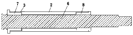
[0017] Example 1, see image 3 , image 3 It is the chain shaft and shaft sleeve structure in the prior art, including carbon steel chain shaft 6, first shaft sleeve 7, second shaft sleeve 8, installation sleeve 2 and groove 3, carbon steel chain shaft 6 is installed on the side of installation sleeve 2 Inside, two grooves 3 are provided on the left and right sides of the inner wall of the installation sleeve 2, the first sleeve 7 is installed in the groove 3 on the left side, and the second sleeve 8 is installed in the groove 3 on the right side. middle. The carbon steel chain shaft 6, the first shaft sleeve 7, and the second shaft sleeve 8 belong to the sliding friction of surface contact. In the environment of unenclosed liquid lubrication, the friction coefficient is high and the wear is fast, because the carbon steel chain shaft 6 and the shaft sleeve cooperate. There is a gap between them, and the butter will liquefy and lose from the gap at high operating temperatures...


PUM


Abstract

The invention discloses a chain shaft and shaft sleeve structure of an automatic woodworking feeder. The chain shaft and shaft sleeve structure comprises a chain shaft, wherein a mounting sleeve is arranged on the outer surface of the chain shaft; grooves are formed in the left side and the right side of the inner wall of the mounting sleeve; rolling bearings are mounted in the grooves; and the inner walls of the rolling bearings are movably connected with the outer surface of the chain shaft. According to the chain shaft and shaft sleeve structure, the chain shaft and shaft sleeve structure is changed into a structure of the chain shaft, the rolling bearings and an oil seal, so that the defects can be effectively overcome; sliding friction is changed into rolling friction, so that the friction coefficient is reduced, and abrasion is reduced; the oil seal can prevent grease from being liquefied and lost, so that sufficient lubrication during friction of the bearings and a shaft neck isguaranteed; meanwhile, dust particles are prevented from entering a friction pair, so that abnormal damage such as pulling and clamping of a friction surface is avoided; and the chain shaft, the rolling bearings and the oil seal are of a completely closed transmission structure, so that grease can be not added for a long time, daily maintenance work is reduced, and great convenience is brought toa user.

Description

technical field [0001] The invention relates to the technical field of chain shafts and shaft sleeves, in particular to the chain shaft and shaft sleeve structure of a woodworking automatic feeder. Background technique [0002] Woodworking automatic feeder is widely used in furniture manufacturing industry for auxiliary feeding during wood processing. Although the structure of the woodworking automatic feeder is improved, the chain shaft and bushing of the transmission part are easy to wear during the use of the common woodworking automatic feeder, as fast as 1-2 months, and as slow as half a year. The shaft and bushing need to be replaced. Even if you regularly clean and maintain it and add butter to increase the hardness of the chain shaft and bushing, the improvement effect will not be great. There are three reasons: First, the chain shaft and bushing belong to the sliding friction of surface contact. Under the environment of liquid lubrication, the friction coefficient ...

Claims


Application Information

Patent Timeline
Patent Type & Authority Applications(China)
IPC IPC(8): F16G15/00F16C11/00F16C19/00F16C33/66F16C33/78
CPCF16C11/00F16C19/00F16C33/664F16C33/7803F16C33/782F16G15/00
Inventor 朱爱平
Owner 朱爱平
Why Eureka
Try Eureka