An automatic drying device for pcb boards

A PCB board and drying device technology, applied in the field of PCB board manufacturing, can solve the problems of long preparation time, secondary wetting of PCB board, high energy consumption of oven, etc., so as to save working hours and labor costs, save manual loading, The effect of accelerating the drying speed

Active Publication Date: 2020-12-29
ANHUI TIANBING ELECTRONICS TECH
View PDF1 Cites 1 Cited by
  • Summary
  • Abstract
  • Description
  • Claims
  • Application Information

AI Technical Summary

Problems solved by technology

[0002] The PCB board needs to be dried during the board making process. The existing drying equipment uses an air knife to blow high-pressure and high-temperature gas to the PCB board to remove water stains on its surface. ) to remove the water, it often takes a long time to dry to remove it, resulting in high energy consumption of the oven and low production efficiency
[0003] In order to improve the drying efficiency, the Chinese Patent Publication No. CN105546939B discloses a centrifugal automatic drying device for PCB boards. Although the drying efficiency can be improved to a certain extent, the following defects still exist: 1. The room is arranged in parallel, and the moisture on the inner PCB board is easily dumped on the adjacent outer PCB board, resulting in secondary wetting of the PCB board, which is not conducive to the improvement of the overall drying efficiency; 2. The entire drying process The drying process is carried out in a closed environment, which is not conducive to the discharge of water, and the heating tube is used for drying. Since the temperature needs to be raised to the set temperature, the preparation work takes a long time, which restricts the improvement of the overall efficiency; 3. PCB board The feeding method is still manually added, and the efficiency is low

Method used


Image

  • An automatic drying device for pcb boards
  • An automatic drying device for pcb boards
  • An automatic drying device for pcb boards

Examples


Embodiment Construction

[0027] In order to make the technical means, creative features, goals and effects achieved by the present invention easy to understand, the present invention will be further described below in conjunction with specific embodiments.

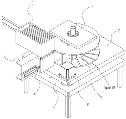
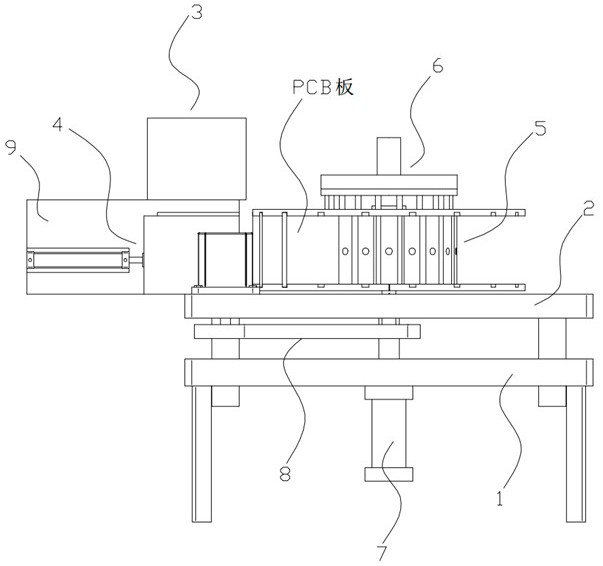
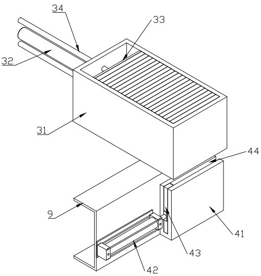
[0028] Such as Figure 1 to Figure 11 As shown, an automatic drying device for PCB boards includes a workbench 1, a base 2, a feeding assembly 3, a lifting assembly 4, a turntable mechanism 5, a positioning mechanism 6, and a lifting assembly 7. The base 2 is slidably connected to On the workbench 1, the adjustment of its height is realized by means of the lifting assembly 7. The feeding assembly 3 is installed on the top of the support plate 9 on the base 2 and can automatically send the PCB board into the ejecting assembly 4. The material assembly 4 is installed on one side of the support plate 9 and is located below the feeding assembly 3. The ejector assembly 4 can send the PCB board into the turntable mechanism 5, and it will be clamped by th...


PUM


Abstract

The invention discloses an automatic drying device for PCBs, and relates to the technical field of PCB manufacturing. The automatic drying device for the PCBs comprises a workbench, a base, a feedingassembly, an ejection assembly, a rotating disc mechanism, a positioning mechanism and a lifting assembly. According to the automatic drying device for the PCBs, the radical arrangement mode are adopted for the PCBs, firstly, due to the rotation of the PCBs, water in micropores in the PCBs can be thrown out, secondly, due to the fact that the arrangement direction of the PCBs is located in the radical direction of stand columns, the water can be thrown out to the outer side along the surfaces of the PCBs under the action of centrifugal force, meanwhile, under the cooperation of hot air passingthrough every two adjacent PCBs, the water can be quickly taken away, the PCBs are heated and dried, and the drying speed of the PCBs is increased.

Description

technical field [0001] The invention belongs to the technical field of PCB board manufacturing, and in particular relates to an automatic drying device for PCB boards. Background technique [0002] The PCB board needs to be dried during the board making process. The existing drying equipment uses an air knife to blow high-pressure and high-temperature gas to the PCB board to remove water stains on its surface. ) to remove the water, it often takes a long time to dry to remove it, resulting in high energy consumption of the oven and low production efficiency. [0003] In order to improve the drying efficiency, the Chinese Patent Publication No. CN105546939B discloses a centrifugal automatic drying device for PCB boards. Although the drying efficiency can be improved to a certain extent, the following defects still exist: 1. The room is arranged in parallel, and the moisture on the inner PCB board is easily dumped on the adjacent outer PCB board, resulting in secondary wettin...

Claims


Application Information

Patent Timeline
Patent Type & Authority Patents(China)
IPC IPC(8): F26B5/08F26B3/06F26B21/00F26B25/00F26B25/02
CPCF26B3/06F26B5/08F26B21/001F26B21/004F26B25/00F26B25/003F26B25/02
Inventor 张东响祁伟尤志刚胡仕伟薛小浪
Owner ANHUI TIANBING ELECTRONICS TECH
Why Eureka
Try Eureka