
Spot welding equipment for PCB production

A technology for PCB circuit boards and spot welding equipment, applied in welding equipment, auxiliary welding equipment, welding/cutting auxiliary equipment, etc., can solve the problems of up and down fluctuations, inaccurate welding of electrical components, and insufficient clamping of the left and right PCB circuit boards. , to achieve the effect of increasing the area

Inactive Publication Date: 2020-04-07
时启艳
View PDF7 Cites 2 Cited by
  • Summary
  • Abstract
  • Description
  • Claims
  • Application Information

AI Technical Summary

Problems solved by technology

[0004] The purpose of the present invention is to solve the problem that in the prior art, when the PCB circuit board is artificially clamped, the operator is afraid that the clamping is too tight and the circuit board is damaged, so that the left and right clamping of the PCB circuit board is not firm enough, and it is easy to weld when welding. Up and down fluctuations lead to inaccurate welding of electrical components, which affects the normal use of PCB circuit boards, and a spot welding equipment for PCB circuit board production is proposed

Method used

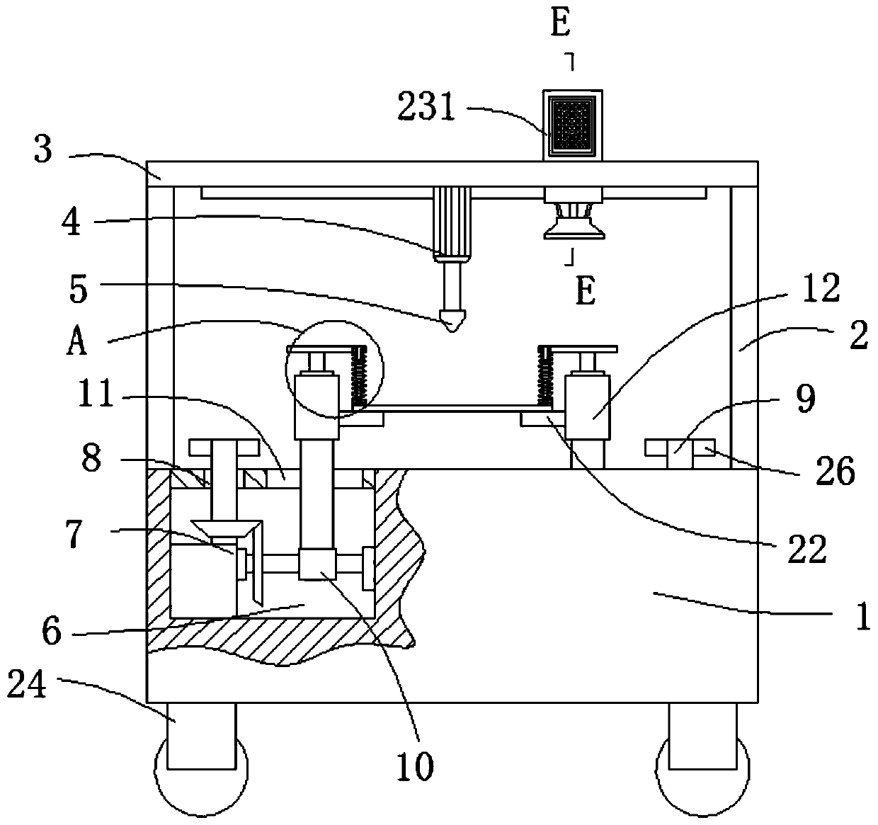

Image

  • Spot welding equipment for PCB production
  • Spot welding equipment for PCB production
  • Spot welding equipment for PCB production

Examples


Embodiment Construction

[0023] The following will clearly and completely describe the technical solutions in the embodiments of the present invention with reference to the accompanying drawings in the embodiments of the present invention. Obviously, the described embodiments are only some, not all, embodiments of the present invention.

[0024] In describing the present invention, it should be understood that the terms "upper", "lower", "front", "rear", "left", "right", "top", "bottom", "inner", " The orientation or positional relationship indicated by "outside", etc. is based on the orientation or positional relationship shown in the drawings, and is only for the convenience of describing the present invention and simplifying the description, rather than indicating or implying that the referred device or element must have a specific orientation, so as to Specific orientation configurations and operations, therefore, are not to be construed as limitations on the invention.

[0025] refer to Figure ...


PUM


Abstract

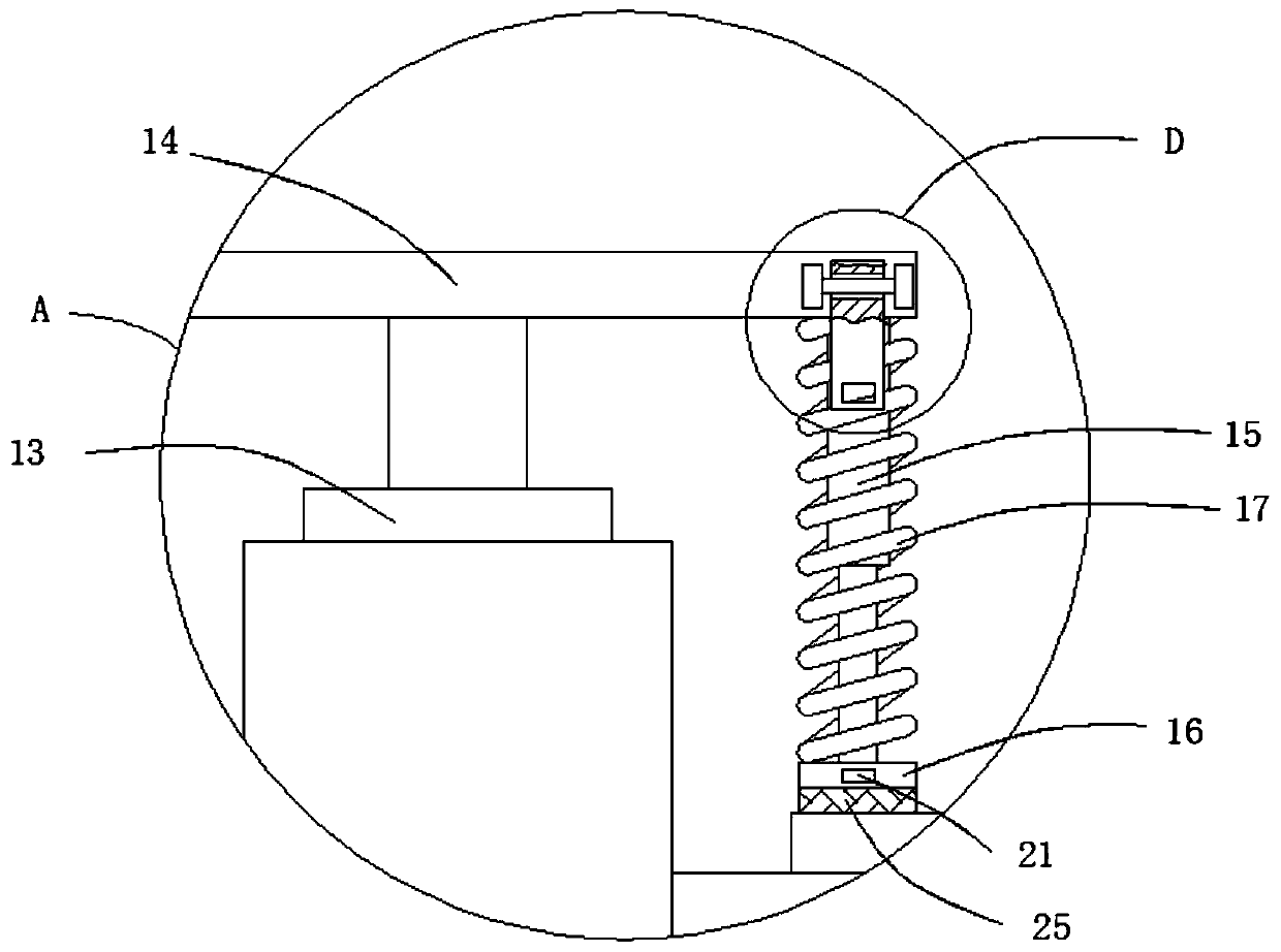
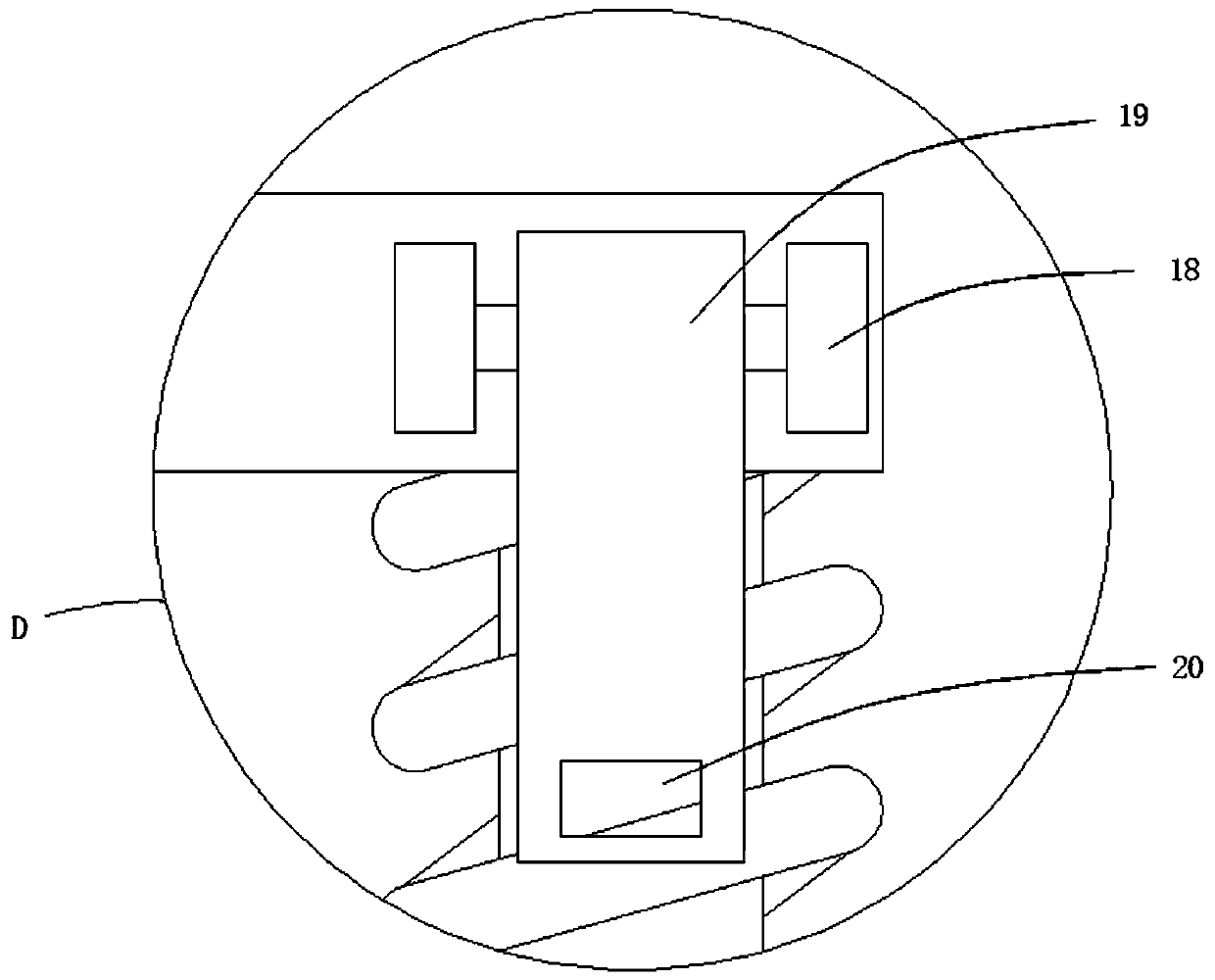
The invention relates to the technical field of circuit board processing, and discloses spot welding equipment for PCB production. The spot welding equipment comprises a base, and two supporting plates are symmetrically and fixedly connected to the upper surface of the base. The upper ends of the two supporting plates are fixedly connected with the same connecting plate; the lower surface of the connecting plate is fixedly connected with a hydraulic push rod; the output end of the hydraulic push rod is fixedly connected with a spot welding gun; two working cavities are formed in the base, andmoving structures are connected into the working cavities; connecting holes are formed in the upper surface of the base; each moving mechanism comprises a handle and a sliding cylinder; the handles extend out of the base through the connecting holes; and sliding holes are formed in the surface of the base. A PCB can be fixed between the two clamping plates from the upper portion, so that the situation that due to the fact that left-right clamping is not firm enough, up-down fluctuation occurs in the welding process is avoided, an air suction cover can be moved circularly in the spot welding process, and the smoke adsorption area is increased.

Description

technical field [0001] The invention relates to the technical field of circuit board processing, in particular to spot welding equipment for PCB circuit board production. Background technique [0002] PCB circuit board, also known as printed circuit board, uses an insulating board as the base material and cuts it to a certain size. At least one conductive pattern is attached to it, and there are holes, which are used to replace the chassis of the electronic components in the past, and realize electronic components. The interconnection between components, in the process of circuit board processing, electrical components need to be soldered to the circuit board. [0003] The spot welding equipment for PCB circuit board production proposed in the patent authorization announcement number CN 110402037A includes a working platform, both sides of the top of the working platform are provided with chutes, and the inside of the chute is provided with The sliders that cooperate with e...

Claims


Application Information

Patent Timeline
Patent Type & Authority Applications(China)
IPC IPC(8): B23K3/00B23K37/04B23K3/08B08B15/04B23K101/42
CPCB08B15/04B23K3/00B23K3/08B23K3/087B23K2101/42
Inventor 时启艳
Owner 时启艳
Learn More