Polishing device for mold machining

A mold processing and longitudinal technology, applied in grinding drive devices, metal processing equipment, grinding machines, etc., can solve the problems of slow positioning speed, inconvenient use of grinding equipment, low grinding efficiency, etc., to achieve simple structure, improve grinding efficiency, Easy-to-use effects

Active Publication Date: 2020-04-07
HUANGHUA RONGTAI MOLD
View PDF7 Cites 11 Cited by
  • Summary
  • Abstract
  • Description
  • Claims
  • Application Information

AI Technical Summary

Problems solved by technology

[0003] In the process of mold preparation, the rough-machined mold needs to be precisely machined, and further grinding is often required. The existing grinding equipment is not convenient enough to use, and the mold needs to be positioned first. The positioning speed is relatively slow, so the grinding efficiency is low.

Method used


Image

  • Polishing device for mold machining
  • Polishing device for mold machining
  • Polishing device for mold machining

Examples


Embodiment 1

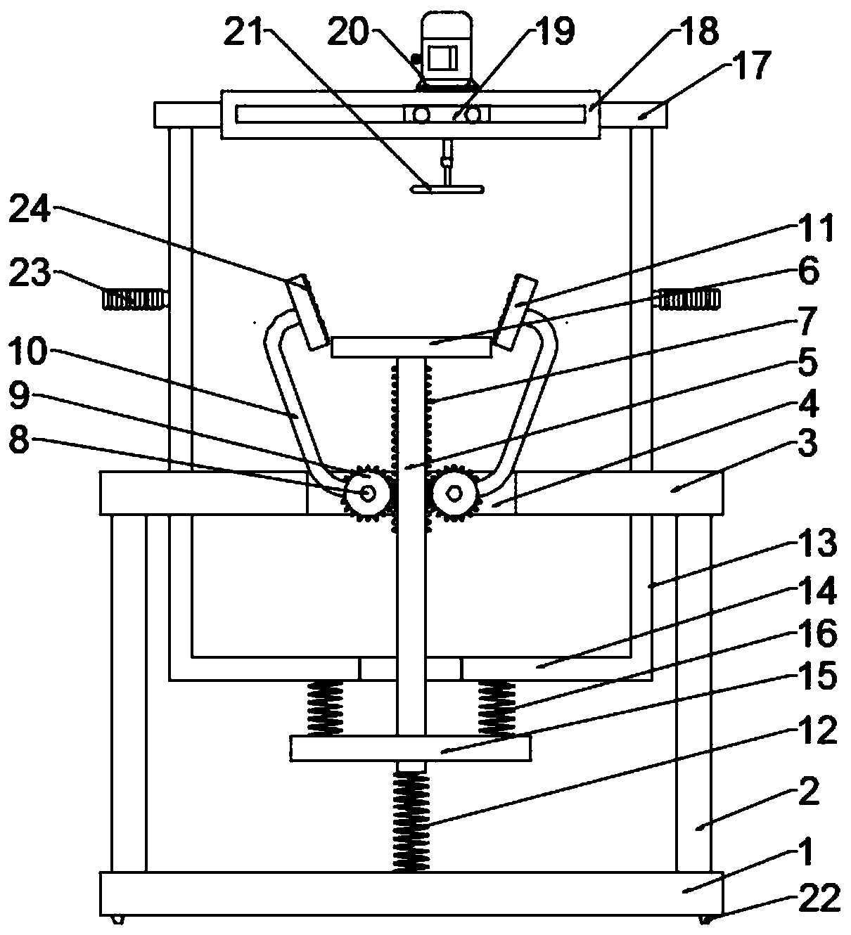
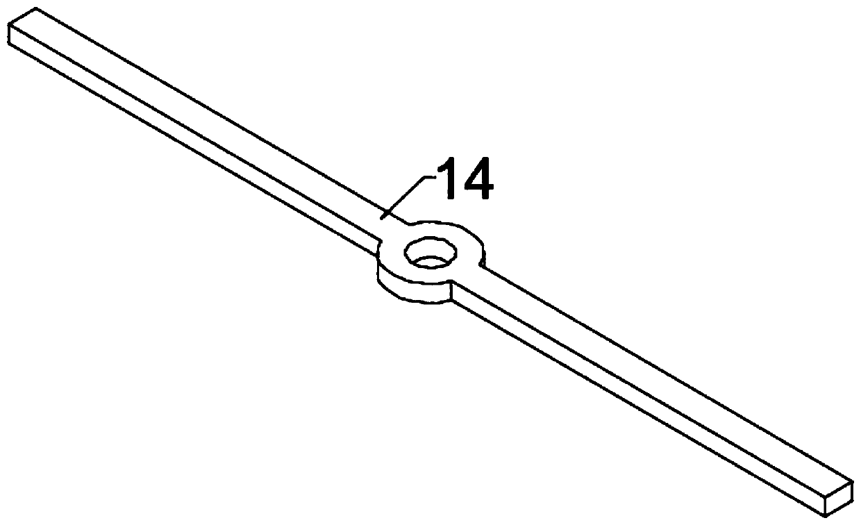
[0022] Example 1: Please refer to figure 1 with image 3 , a grinding device for mold processing, comprising a fixed base plate 1, a support column 2 is fixedly connected symmetrically to the left and right above the fixed base plate 1, an upper table 3 is fixedly connected above the support column 2, and a through groove is opened in the middle of the upper table 3 4. The inner side of the through groove 4 is slidably connected to the longitudinal sliding rod 5, the top of the longitudinal sliding rod 5 is fixedly connected to the supporting base plate 6, and the two sides of the longitudinal sliding rod 5 are fixedly connected to the transmission teeth 7, and the left and right symmetrical fixed connections on the upper table 3 are two The fixed shaft 8 in the through groove 4 and the outside of the fixed shaft 8 are all rotatably connected with a driven gear 9, and the driven gear 9 is meshed with the transmission gear 7, and the outside of the driven gear 9 is fixedly conn...

Embodiment 2

[0034] Example 2: Please refer to figure 2 with image 3 , a grinding device for mold processing, comprising a fixed base plate 1, a support column 2 is fixedly connected symmetrically to the left and right above the fixed base plate 1, an upper table 3 is fixedly connected above the support column 2, and a through groove is opened in the middle of the upper table 3 4. The inner side of the through groove 4 is slidably connected to the longitudinal sliding rod 5, the top of the longitudinal sliding rod 5 is fixedly connected to the supporting base plate 6, and the two sides of the longitudinal sliding rod 5 are fixedly connected to the transmission teeth 7, and the left and right symmetrical fixed connections on the upper table 3 are two The fixed shaft 8 in the through groove 4 and the outside of the fixed shaft 8 are all rotatably connected with a driven gear 9, and the driven gear 9 is meshed with the transmission gear 7, and the outside of the driven gear 9 is fixedly con...


PUM


Abstract

The invention discloses a polishing device for mold machining and relates to a polishing device. The polishing device comprises a fixed bottom plate; supporting stand columns are fixedly connected tothe upper portion of the fixed bottom plate in a bilateral symmetry mode. An upper table board is fixedly connected above the supporting stand columns; a through groove is formed in the middle of theupper table board; longitudinal sliding rods are slidably connected to the inner sides of the through grooves; a supporting bottom plate is fixedly connected to the top of the longitudinal sliding rod, transmission teeth are fixedly connected to the two sides of the longitudinal sliding rod, two fixing shafts located in the through grooves are fixedly connected to the upper table top in a bilateral symmetry mode, driven gears are rotationally connected to the outer sides of the fixing shafts and engaged with the transmission teeth, and connecting swing rods are fixedly connected to the outer sides of the driven gears. The polishing device is simple in structure and convenient to use, a grinding tool needing to be ground is directly placed above the supporting bottom plate of the device inthe using process, then the motor is driven downwards to move downwards, grinding can be achieved, the device can automatically position and clamp the mold, manual adjustment is not needed, and therefore the grinding efficiency is effectively improved.

Description

technical field [0001] The invention relates to a grinding device, in particular to a grinding device for mold processing. Background technique [0002] Mold, various molds and tools used in industrial production for injection molding, blow molding, extrusion, die-casting or forging forming, smelting, stamping and other methods to obtain the required products. In short, a mold is a tool used to make shaped objects. This tool is composed of various parts, and different molds are composed of different parts. It mainly realizes the processing of the shape of the article through the change of the physical state of the formed material. [0003] In the process of mold preparation, the rough-machined mold needs to be precisely machined, and further grinding is often required. The existing grinding equipment is not convenient to use, and the mold needs to be positioned first. The positioning speed is relatively slow, so the grinding efficiency is low. For this reason, those skille...

Claims


Application Information

Patent Timeline
Patent Type & Authority Applications(China)
IPC IPC(8): B24B19/20B24B41/06B24B27/00B24B41/02B24B47/04
CPCB24B19/20B24B27/0046B24B41/02B24B41/06B24B47/04
Inventor 李翠云
Owner HUANGHUA RONGTAI MOLD
Why Eureka
Try Eureka