Additive substrate plane distortion compensating method

A distortion compensation and planar technology, which is applied in the field of electromechanical methods, can solve problems such as high cost, initial deposition layer warping, and complex drive mechanism, so as to reduce material and processing costs, cancel substrate leveling operations, and have high technical feasibility Effect

Inactive Publication Date: 2020-04-07
PERA
View PDF7 Cites 3 Cited by
  • Summary
  • Abstract
  • Description
  • Claims
  • Application Information

AI Technical Summary

Problems solved by technology

When the flatness deviation of the additive substrate is large, it will not only cause warping of the initial deposition layer, which will lead to printing failure, but also cause scratches and collisions between the print head and the additive substrate in severe cases, resulting in major equipment damage accidents
At the same time, in 3D printers, additive substrates are generally designed as quick-disassembly parts and wearing parts. Therefore, relying on improving the mechanical strength of the substrate and improving the processing accuracy to ensure its flatness is not only costly, but also structurally difficult. In terms of design, such as installation space, weight, etc., there are major limitations
[0003] In order to ensure the flatness of the additive substrate in the 3D printing coordinate system, the traditional method generally regards the additive substrate as a rigid whole, and sets manual adjustment bolts at its four corners, and then relies on measuring tools such as feeler gauges and repea

Method used


Image

  • Additive substrate plane distortion compensating method
  • Additive substrate plane distortion compensating method
  • Additive substrate plane distortion compensating method

Examples


Embodiment Construction

[0032] The embodiments of the present invention will be described in detail below in conjunction with the accompanying drawings.

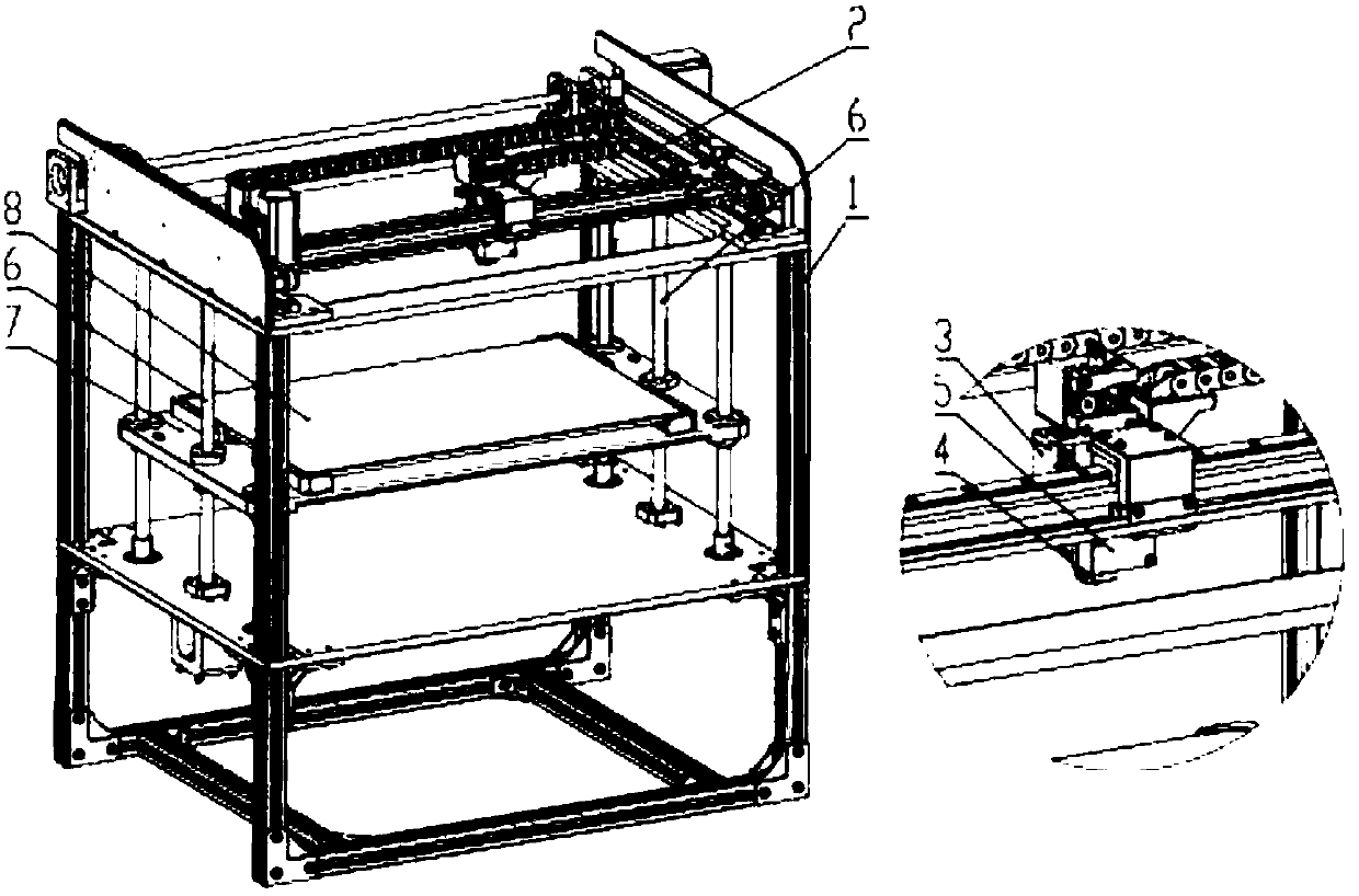
[0033] In order to realize the method for compensating the plane distortion of the additive substrate of the present invention, the corresponding printing device is such as figure 1 As shown, the printing device includes a rigid support 1, an XY-axis positioning mechanism 2, a Z-axis positioning mechanism 6, a first moving platform 3, a second moving platform 7, a forming head 4, a distance measuring head 5, an additive substrate 8, a three-dimensional Print controller 11, where:

[0034] The XY axis positioning mechanism 2 is located on the top of the rigid support 1, and there is a first mobile platform 3 on the XY axis positioning mechanism 2; the first mobile platform 3 has a shaping head 4 and a distance measuring head 5, wherein the The shaping head 4 and the distance measuring head 5 use the XY-axis positioning mechanism 2 to perform planar motio...


PUM


Abstract

The invention discloses an additive substrate plane distortion compensating method. A distance measuring head is used, and plane distortion data on the surface of an additive substrate are scanned andmeasured; parameters such as a plane distortion compensation value are calculated by a three-dimensional printing controller, and a forming action head is controlled to follow additive substrate surface distortion and implement deposition operation; in the process of printing a plane distortion compensation base, by real-time adjustment of the deposition compensation amount of the forming actionhead, plane distortion of the additive substrate is cumulatively compensated layer by layer; and finally an upper surface close to an ideal plane is obtained on the finally-completed plane distortioncompensation base, and upper surface is used as a reference plane for a three-dimensional printed part. By means of the method, high flatness of the additive substrate does not need to be ensured, complicated and precise multi-point leveling mechanisms are not needed, large-format deposition additive operation can be realized, and the material and processing cost of the additive substrate can be reduced.

Description

Technical field [0001] The invention belongs to the category of electromechanical methods, and specifically relates to a plane distortion compensation method. Background technique [0002] With the rapid development of 3D printing technology, the application of 3D printed parts, especially large-sized parts, has developed rapidly. In the process of using fused deposition methods, such as FDM (Fused Deposition Modeling) and LMD (Laser Fused Deposition) to print large-size plastic or metal three-dimensional parts, it is used as an additive substrate for the deposition starting surface and reference surface, and its flatness is required Also getting higher. When the flatness deviation of the additive substrate is large, it will not only cause the initial deposition layer to warp and cause printing failure, but also cause the print head and the additive substrate to scratch and collide, causing major equipment damage accidents. At the same time, in 3D printers, additive substrates ...

Claims


Application Information

Patent Timeline
IPC IPC(8): B29C64/245B29C64/393B33Y50/02
CPCB29C64/245B29C64/393B33Y50/02
Inventor 俞红祥应华
Owner PERA
Why Eureka
Try Eureka