OVD deposition cavity device for preparing optical fiber preform

An optical fiber preform and deposition cavity technology, applied in the field of OVD deposition, can solve the problems of cut-off wavelength, poor mode field diameter stability, low collection efficiency, small package area, etc., and achieves improved deposition collection rate, simple control process, The effect of increased package area

Active Publication Date: 2020-04-07
JIANGSU FASTEN PHOTONICS +2
View PDF9 Cites 3 Cited by
  • Summary
  • Abstract
  • Description
  • Claims
  • Application Information

AI Technical Summary

Problems solved by technology

[0005] 1. The uniformity of cooling gas flow rate distribution in the axial direction of the loose body is not good: the structure of the OVD deposition chamber tends to fluctuate periodically along the axial direction of the loose body because the flow rate of a single lampshade from the center to the outside is high in the middle and low at the side. The outer diameter of the final deposited preform fluctuates, which affects the quality of the preform, such as the poor stability of cut-off wavelength and mode field diameter
[0006] 2. The collection efficiency of soot is low: the existing OVD deposition chamber structure, the flow direction of the cooling gas cannot be effectively controlled, resulting in a small contact area between the deposition flame and the soot, that is, the wrapping area of ​​the soot by the deposition flame is small, A lot of SiO 2 The powder is not deposited on the surface of the loose body, but is directly sucked away with the airflow, resulting in a low collection efficiency, generally between 45% and 50%.
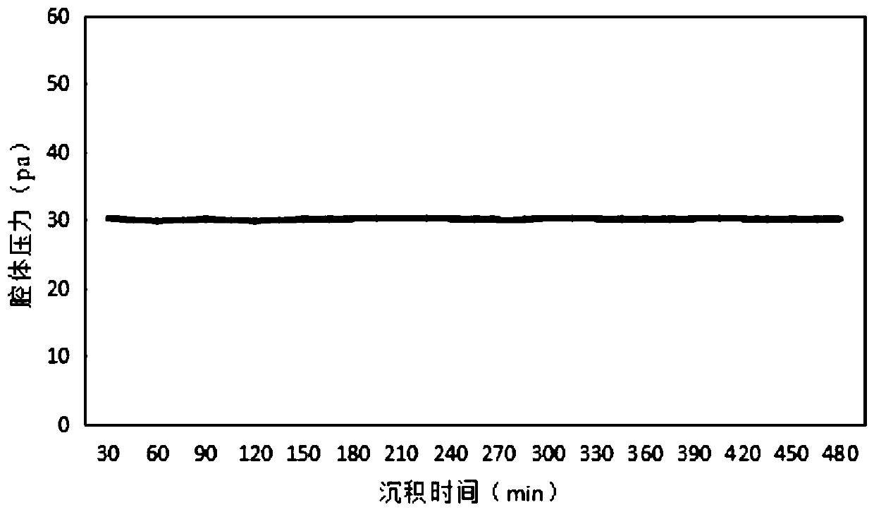
[0007] 3. The cavity pressure cannot be controlled online: the existing OVD deposition cavity device adopts an offline control method for the cavity pressure
In such a state, the pressure of the cavity will drop due to the continuous growth of the loose body or the continuous accumulation of dust in the air flow pipe, which may eventually cause the tail gas generated by the deposition to be unable to be pumped out in time, a large amount of dust will accumulate in the deposition cavity, and the remaining dust will fall. to the soot, forming impurity defects in the preform
[0008] 4. Not conducive to cleaning: the current deposition chamber has airflow dead angles, and most of these airflow dead angles are also hygienic dead angles that are difficult to be purged
Especially the back of the exhaust hood is easy to accumulate dust. If the dust falls on the loose body during the deposition process, it is easy to form impurity defects such as "white spots" in the soot

Method used


Image

  • OVD deposition cavity device for preparing optical fiber preform
  • OVD deposition cavity device for preparing optical fiber preform
  • OVD deposition cavity device for preparing optical fiber preform

Examples


Embodiment Construction

[0031] The present invention will be further described in detail below with reference to the embodiments of the drawings, examples of which are shown in the drawings, wherein the same or similar reference numerals represent the same or similar elements or elements with the same or similar functions. The embodiments described below by referring to the figures are exemplary and are intended to explain the present invention and should not be construed as limiting the present invention.

[0032] The terms "first" and "second" are used for descriptive purposes only, and cannot be understood as indicating or implying relative importance or implicitly specifying the quantity of indicated technical features. Thus, a feature defined as "first" and "second" may explicitly or implicitly include one or more of these features. In the description of the present invention, "plurality" means two or more, unless otherwise specifically defined.

[0033] In the present invention, unless otherwi...


PUM

PropertyMeasurementUnit
diameteraaaaaaaaaa
diameteraaaaaaaaaa
diameteraaaaaaaaaa

Abstract

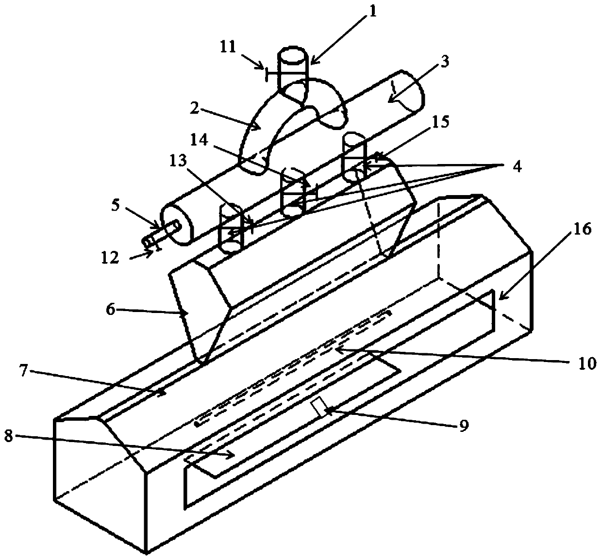
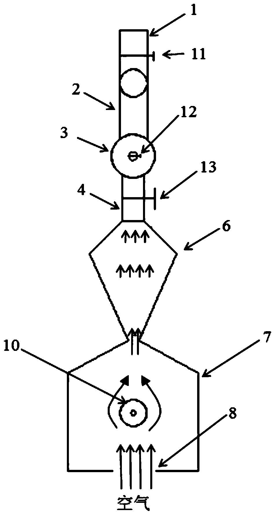
The invention relates to an OVD deposition cavity device for preparing an optical fiber preform. The device comprises an exhaust pipe, a first-stage buffer chamber, a second-stage buffer chamber and adeposition chamber, wherein the exhaust pipe, the first-stage buffer chamber, the second-stage buffer chamber and the deposition chamber are sequentially arranged from top to bottom, a wind inlet isformed in the bottom of the deposition chamber, a deposition core rod and a deposition blow lamp are arranged in the deposition chamber, the deposition chamber is in a house shape, the upper portion of the deposition chamber is trapezoidal, the lower portion of the deposition chamber is square, the top of the deposition chamber is in butt joint with the slit of the second-stage buffer chamber, thelower portion of the second-stage buffer chamber is inverted trapezoidal, the first-stage buffer chamber is in a circular tube shape, a wind supplementing pipe is arranged on the end surface of the first-stage buffer chamber, a wind supplementing valve is arranged on the wind supplementing pipe and used for adjusting the opening and closing size of the wind supplementing pipe, the first-stage buffer chamber is vertically communicated with the second-stage buffer chamber through a plurality of second-stage branch pipes distributed side by side in the axial direction, and the exhaust pipe is communicated with the first-stage buffer chamber through two arc-shaped pipes in a bilateral symmetry manner. According to the invention, the distribution uniformity of the gas flow in the deposition chamber along the axial direction of the deposition core rod is improved, the air pressure in the deposition chamber is stabilized, the wrapping area of the flame of the blow lamp on the deposition corerod is increased, and the collection rate of SiO2 powder is increased.

Description

technical field [0001] The present invention relates to OVD deposition in the field of optical fiber fabrication. Background technique [0002] With the rapid development of the communication industry, major manufacturers are competing to expand production capacity, resulting in overcapacity, and the price of optical fiber has almost halved. How to control the cost of optical fiber production and increase market share has become the key to the survival of enterprises. At present, the mainstream optical fiber preform preparation technology is: VAD+OVD process, that is: the core rod is prepared by the VAD process; the cladding is prepared by the OVD process. The cladding cost accounts for more than 90% of the cost of the preform. Therefore, under the current situation, how to reduce the cost of the OVD process is the key to forming the competitiveness of enterprises. [0003] The OVD cavity has an important impact on the cost and quality of the optical fiber preform. On the...

Claims


Application Information

Patent Timeline
Patent Type & Authority Applications(China)
IPC IPC(8): C03B37/014C03B37/018
CPCC03B37/0142C03B37/01815Y02P40/57
Inventor 江锋钱昆黄本华刘瑞林孙周严薇
Owner JIANGSU FASTEN PHOTONICS
Why Eureka
Try Eureka