Induction quenching process for hardening alloy cast iron camshaft by using compressed air

An alloy cast iron, compressed air technology, applied in the field of heat treatment, can solve the problems of exceeding the ultimate strength, economic losses of enterprises, and failing to meet the hardness index requirements, and achieve the reduction of the possibility of cracking, uniform internal and external temperatures, and good performance indicators. Effect

Inactive Publication Date: 2020-04-07
荆州环球汽车零部件制造有限公司
View PDF3 Cites 4 Cited by
  • Summary
  • Abstract
  • Description
  • Claims
  • Application Information

AI Technical Summary

Problems solved by technology

According to statistics, when the camshaft is induction hardened by the traditional process, the ratio of cracks at the lift of the camshaft during the heating stage is 35-40%; Due to the excessive quenching stress in the cooling process, which exceeds the ultimate strength of the workpiece, quenching cracks appear in a large number of workpieces. The use of traditional quenching technology leads to a high reject rate, which causes huge economic losses to the enterprise.
According to statistics, the crack rate produced by water quenching is 100%, the crack rate is 30-35% when quenched with a water-soluble quenching agent with a concentration of 10-15%, and the quenching crack rate is also 10-15% when sprayed with a water-based quenching agent. , if air cooling and quenching is used after heating, although it will not cause cracking of the workpiece, it will not meet the hardness index requirements in the technical requirements
Therefore, the scrap rate produced by the traditional induction hardening process is extremely high, which greatly increases the production cost and causes great troubles to the enterprise. Even if the products pass the inspection, there are still uncertain quality hidden dangers, which directly affect the quality of the enterprise. reputation

Method used


Image

  • Induction quenching process for hardening alloy cast iron camshaft by using compressed air

Examples


Embodiment 1

[0022] Embodiment 1, 30 camshaft workpieces, carry out induction hardening according to the following method:

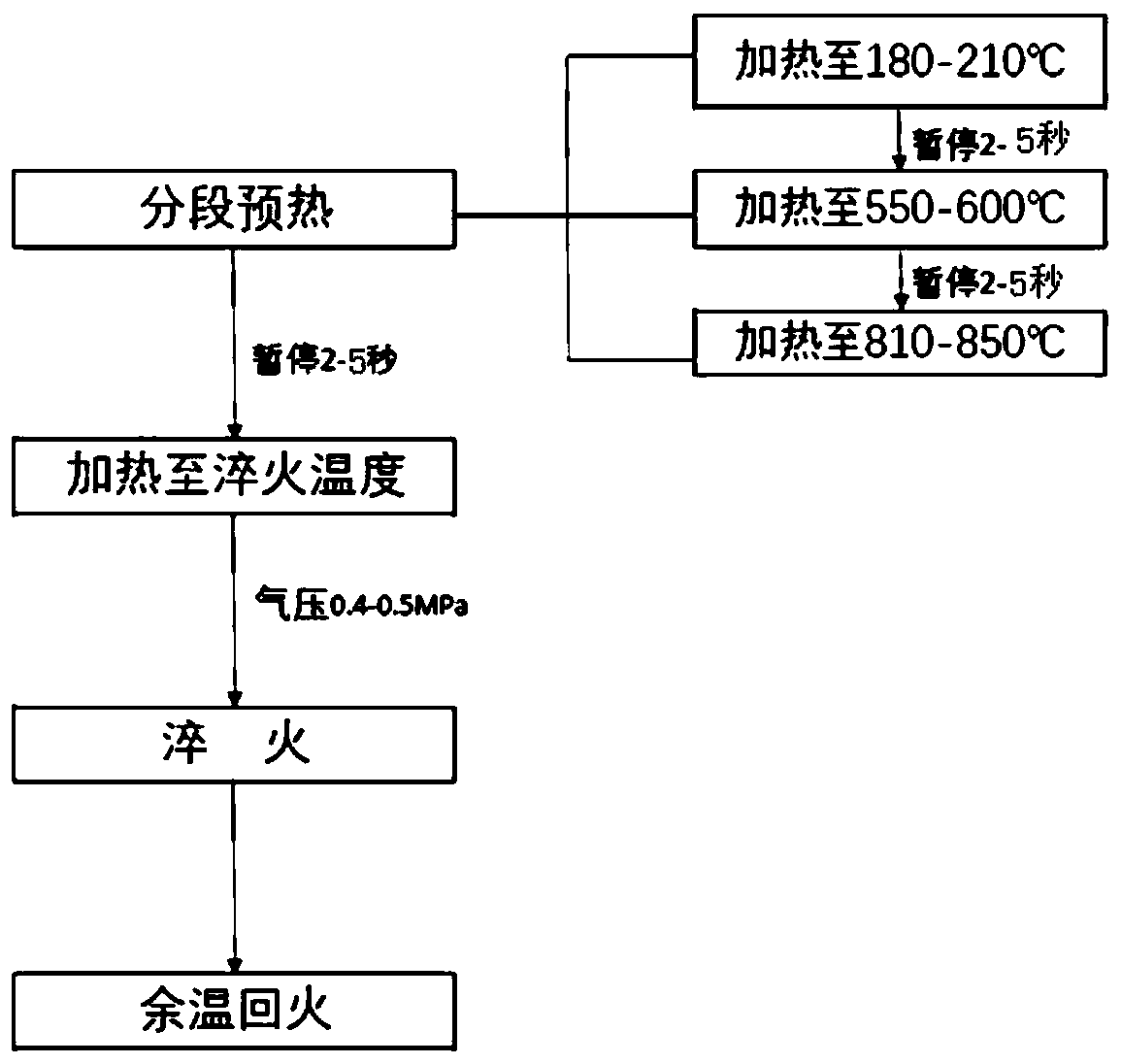
[0023] S1. Preheating: first heat the camshaft to 190±10°C by induction, stop heating for 2 seconds to ensure that the heating part is evenly heated, then induction heat to 560±10°C, stop heating for 2 seconds; then induction heat the camshaft to 820±10°C, stop heating for 2 seconds; the heating rate of the three stages is 40-50°C / s;

[0024] S2. Heating to the quenching temperature: induction heating the camshaft preheated in step S1 to 900±10° C. at a heating rate of 40-50° C. / second;

[0025] S3. Quenching: using compressed air with a pressure of 0.4-0.5 MPa as the quenching medium, quenching the camshaft heated in step S2 for 50 seconds, and cooling the camshaft to 250-280° C.;

[0026] S4. Tempering at residual temperature: the camshaft quenched in step S3 is left at room temperature for 50 minutes, and the tempering process is completed by utilizing the residu...

Embodiment 2

[0027] Embodiment 2, 30 camshaft workpieces, carry out induction hardening according to the following method:

[0028] S1. Preheating: first heat the camshaft induction to 200±10°C, stop heating for 5 seconds to ensure that the heating part is evenly heated, then induction heat to 590±10°C, stop heating for 5 seconds; then induction heat the camshaft to 840±10°C, stop heating for 5 seconds; the heating rate of the three stages is 40-50°C / s;

[0029] S2. Heating to the quenching temperature: induction heating the camshaft preheated in step S1 to 930±10°C at a heating rate of 40-50°C / s;

[0030] S3. Quenching: using compressed air with a pressure of 0.4-0.5 MPa as the quenching medium, quenching the camshaft heated in step S2 for 40 seconds, and cooling the camshaft to 270-300° C.;

[0031] S4. Tempering at residual temperature: the camshaft quenched in step S3 is left at room temperature for 60 minutes, and the tempering process is completed by utilizing the residual temperatu...

Embodiment 3

[0032] Embodiment 3, 30 camshaft workpieces, carry out induction hardening according to the following method:

[0033] S1. Preheating: first heat the camshaft to 190±10°C by induction, stop heating for 3 seconds to ensure that the heating part is evenly heated, then induction heat to 570±10°C, stop heating for 3 seconds; then induction heat the camshaft to 830±10°C, stop heating for 3 seconds; the heating rate of the three stages is 40-50°C / s;

[0034] S2. Heating to the quenching temperature: induction heating the camshaft preheated in step S1 to 920±10°C at a heating rate of 40-50°C / s;

[0035] S3. Quenching: using compressed air with a pressure of 0.4-0.5 MPa as the quenching medium, quenching the camshaft heated in step S2 for 40 seconds, and cooling the camshaft to 260-290° C.;

[0036] S4. Tempering at residual temperature: the camshaft quenched in step S3 is left at room temperature for 50 minutes, and the tempering process is completed by utilizing the residual temper...


PUM


Abstract

The invention provides an induction quenching process for hardening an alloy cast iron camshaft by using compressed air, which comprises the following steps: S1, preheating is carried out: the camshaft is heated to 180-210 DEG C in an induction manner in a first stage, heating is suspended for 2-5 seconds, in a second stage, after the camshaft is inductively heated to 550-600 DEG C, heating is suspended for 2-5 seconds, and in a third stage, after the camshaft is inductively heated to 810-850 DEG C, heating is suspended for 2-5 seconds, wherein the heating rates of the three stages are all 40-50 DEG C / s; S2, heating to a quenching temperature is carried out: induction heating is carried out on the camshaft preheated in the step S1 to 900-940 DEG C at a heating rate of 40-50 DEG C / s; S3, quenching is conducted, specifically, compressed air with the pressure of 0.4-0.5 MPa is adopted as a quenching medium to quench the camshaft, and the camshaft is cooled to 250-300 DEG C; and S4, afterheat tempering is carried out. The alloy cast iron camshaft product quenched by using the process method disclosed by the invention does not crack in the quenching process, and the hardness index of the quenched alloy cast iron camshaft product can meet the technical requirements, so that the rejection rate of the product is reduced, and the production cost is greatly saved.

Description

technical field [0001] The invention relates to an induction hardening process using compressed air to harden an alloy cast iron camshaft, and belongs to the technical field of heat treatment. Background technique [0002] Alloy cast iron camshafts are important moving parts in internal combustion engines, and the market demand is large. After induction hardening, alloy cast iron camshafts have significantly better wear resistance than steel products, so induction hardening is an indispensable process. . However, in the traditional induction hardening heat treatment process, cracks inevitably appear, and there are two types of cracks, one is heating cracks, and the other is quenching cracks. The two kinds of cracks are mainly concentrated in the lift parts on both sides of the cam lobe. According to statistics, when the camshaft is induction hardened by the traditional process, the ratio of cracks at the lift of the camshaft during the heating stage is 35-40%; Due to the ...

Claims


Application Information

Patent Timeline
IPC IPC(8): C21D9/30C21D1/10C21D1/613C22C37/08C22C37/10C21D1/18
CPCC21D1/10C21D1/18C21D1/613C21D9/30C22C37/08C22C37/10Y02P10/20Y02P10/25
Inventor 王天保刘军凯
Owner 荆州环球汽车零部件制造有限公司
Why Eureka
Try Eureka