Supercharge Your Innovation With Domain-Expert AI Agents!

Conduction oil heating system

A heating system and heat transfer oil technology, applied in the field of heat transfer oil heating, can solve the problems of uneven temperature of heating equipment, decrease of heat transfer efficiency of heat transfer oil, and non-aggregation of heat transfer oil temperature, so as to achieve uniform and stable heat transfer and improve temperature uniformity. , temperature uniform and stable effect

Inactive Publication Date: 2020-04-07
武汉欣力瑞机电设备有限公司
View PDF0 Cites 0 Cited by
  • Summary
  • Abstract
  • Description
  • Claims
  • Application Information

AI Technical Summary

Problems solved by technology

The heating system of this heating method has the characteristics of simple appearance, compact structure, and convenient operation. However, during the production process, the electric heating tube directly contacts the heat transfer oil for heating. The maximum allowable working temperature is generally around 300 degrees Celsius. Due to the carbonization and deterioration of the heat transfer oil due to local long-term high temperature, the heat transfer efficiency of the heat transfer oil continues to decline. It is very difficult to clean the inner wall of the heating tank
In addition, the existing heating tank or heating ax is usually designed in the shape of a cylindrical tank. This shape of the heating tank is very easy to cause heat dispersion, and the heat conduction oil is heated unevenly, resulting in uneven and uneven temperature output to the heating equipment. Stable; the temperature of the heat transfer oil in the heating tank does not accumulate, the heat is easily lost, the heat storage effect is poor, and the energy consumption is large
In order to improve energy efficiency, the heat transfer oil heating system currently on the market adopts the most method of changing the shape or structure of the electric heater, such as designing the electric heater in a spiral shape to increase its contact surface with the heat transfer oil, but this change is also at the same time Increased power consumption

Method used


Image

  • Conduction oil heating system
  • Conduction oil heating system
  • Conduction oil heating system

Examples


Embodiment Construction

[0024] The principles and features of the present invention are described below in conjunction with the accompanying drawings, and the examples given are only used to explain the present invention, and are not intended to limit the scope of the present invention.

[0025] The present invention will be further described in detail below in conjunction with the accompanying drawings and specific embodiments.

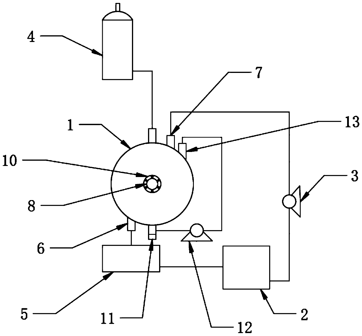
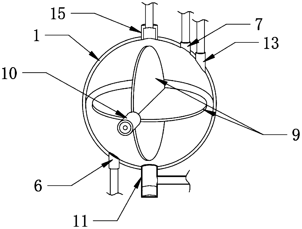
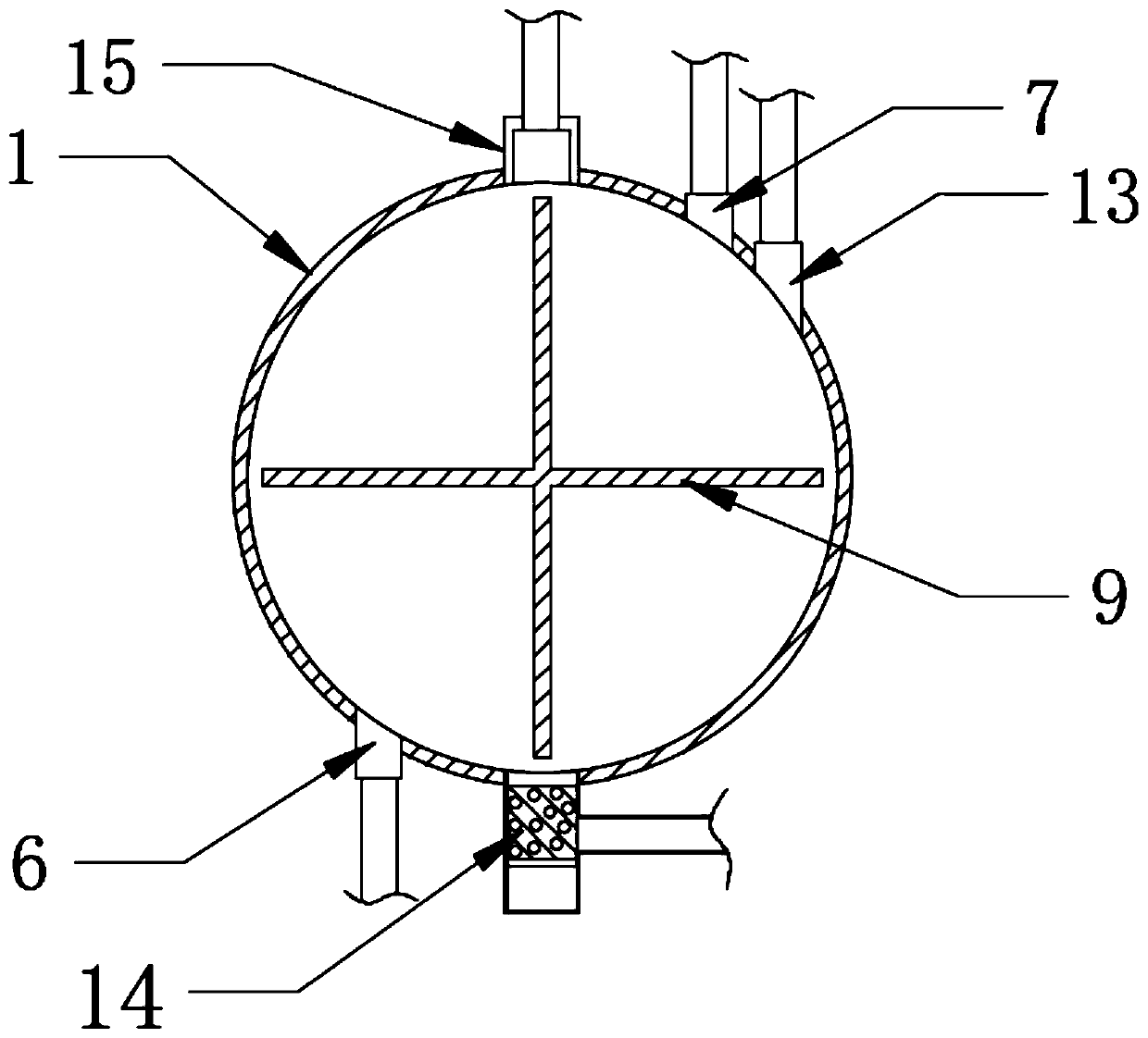
[0026] Such as Figure 1~3 The heat transfer oil heating system shown includes a heat transfer oil heating cycle system and a heat transfer oil impurity removal cycle system;

[0027] The heat supply circulation system of heat conduction oil includes a heating tank 1, a heating device, a storage tank 2, a heat supply circulation pump 3, a high level tank 4 and a heat utilization equipment 5; the heating tank 1 is a hollow spherical tank filled with heat conduction oil;

[0028] The heating tank 1 is provided with a heat transfer oil outlet 6 and a heat transfer oil inlet 7...


PUM


Abstract

The invention discloses a conduction oil heating system which comprises a heat supply circulating system and an impurity removal circulating system. The heat supply circulating system comprises a heating tank, a heating device, a storage tank, a heat supply circulating pump, an elevated tank and heat utilization equipment; the heating tank is a hollow spherical tank body and is filled with heat conduction oil; the heating tank is provided with a heat conduction oil outlet and a heat conduction oil inlet which are arranged in a diametric point manner; the conduction oil impurity removal circulating system comprises a precipitation cup, an impurity removal circulating pump and an oil return port formed in the heating tank; and the side wall of the precipitation cup, the impurity removal circulating pump and the oil return port are sequentially communicated through an impurity removal oil pipe. The system has the beneficial effects that the heating tank is spherical, heat is gathered andis not easy to disperse, heat conduction is uniform and stable, and the temperature of heat conduction oil in the heating tank is kept uniform and stable; stable temperature supply can be provided forheat utilization equipment; sediments in the heating tank can be effectively collected, and the heat conduction efficiency of heat conduction oil is guaranteed.

Description

technical field [0001] The invention relates to the technical field of heat conduction oil heating, in particular to a heat conduction oil heating system. Background technique [0002] Traditional heat transfer oil fuel heaters use coal, heavy oil, light oil, combustible gas or other combustible materials as fuel, use heat transfer oil as the heat carrier, and use circulating oil pumps to force liquid phase circulation to transfer heat energy to heat-consuming equipment and then return Reheating once-through special industrial furnace. However, the temperature of the heat transfer fluid in the furnace is high, and most of them are flammable and explosive. Once leakage occurs during operation, it will cause fire, explosion and other accidents, and even cause casualties and property losses. The heat conduction oil electric heater is a new type, safe, high-efficiency and energy-saving, low-pressure (atmospheric or lower pressure) and special industrial furnace that can provide...

Claims


Application Information

Patent Timeline
IPC IPC(8): F24H7/00F24H9/00F24H9/02F24H9/18F24H9/20
CPCF24H7/00F24H9/00F24H9/0042F24H9/02F24H9/1809F24H9/2007
Inventor 不公告发明人
Owner 武汉欣力瑞机电设备有限公司
Features
  • R&D
  • Intellectual Property
  • Life Sciences
  • Materials
  • Tech Scout
  • Unparalleled Data Quality
  • Higher Quality Content
  • 60% Fewer Hallucinations
Learn More