Method for manufacturing liquid crystal display element

A technology of liquid crystal display element and manufacturing method, which is applied in nonlinear optics, instruments, optics and other directions, and can solve the problem that the orientation directions of liquid crystal molecules are not sufficiently consistent.

Pending Publication Date: 2020-04-07
DIC CORP
View PDF2 Cites 1 Cited by
  • Summary
  • Abstract
  • Description
  • Claims
  • Application Information

AI Technical Summary

Problems solved by technology

Therefore, it is desired to reduce the voltage applied to the liquid crystal composition as much as possible, but in the conventional method, if the voltage applied to the liquid crystal composition is reduced, depending on the configuration of the electrodes, etc., the alignment directions of the liquid crystal molecules may not be sufficiently aligned, or It takes a long time until the alignment directions are fully aligned

Method used


Image

  • Method for manufacturing liquid crystal display element
  • Method for manufacturing liquid crystal display element
  • Method for manufacturing liquid crystal display element

Examples


Embodiment 1

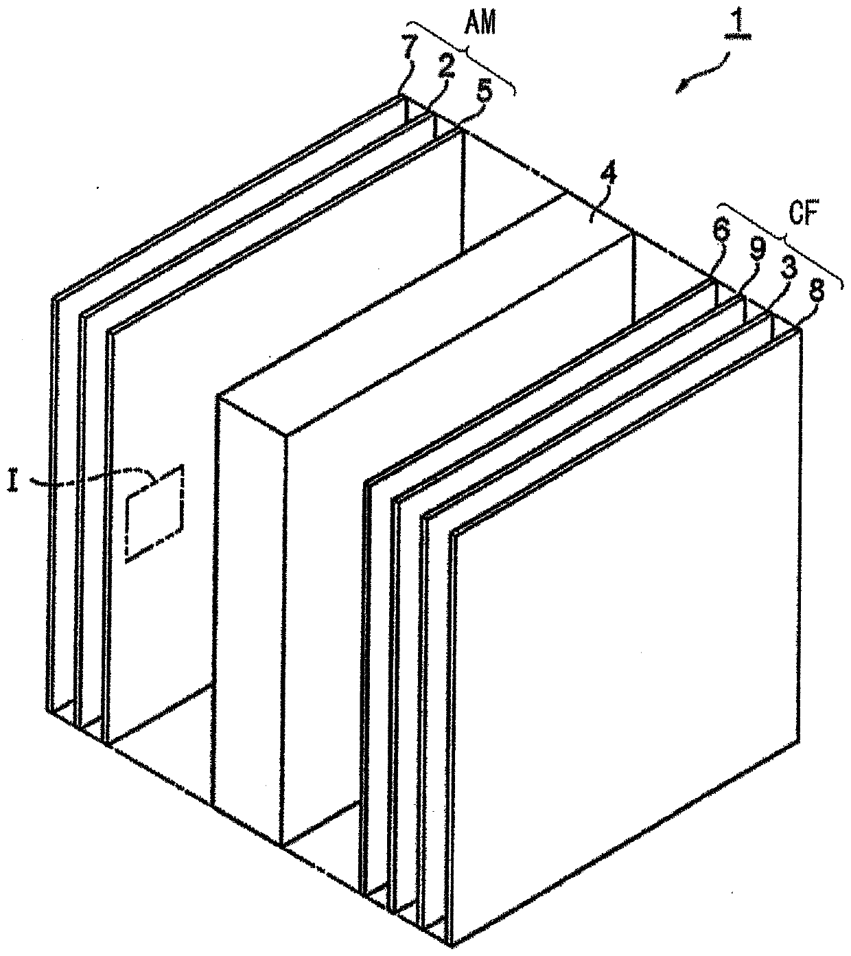
[0659] First, after coating the polyimide film on the ITO substrate, the polyimide film is rubbed to form an alignment film. Then, an empty liquid crystal cell (cell gap 3.5 μm) including an ITO substrate with an alignment film was produced.

[0660] Next, the liquid crystal composition is injected into the empty liquid crystal cell by a vacuum injection method.

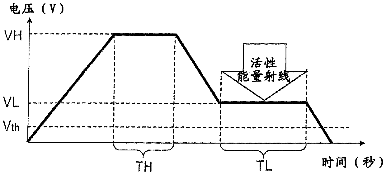
[0661] Next, to the liquid crystal cell in which the liquid crystal composition was injected, an AC voltage of 4.6 V (first voltage VH) was applied at a frequency of 100 Hz, and this state was maintained for 30 seconds. Next, the AC voltage is lowered to 4V (second voltage VL), and while maintaining this state, ultraviolet rays are irradiated through a filter that filters ultraviolet rays having a wavelength of 325 nm or less from the high-pressure mercury lamp.

[0662] At this time, the illuminance measured under the condition of the center wavelength of 365nm becomes 100mW / cm 2 Set the way to irradiate ultraviolet light...

Embodiment 2

[0664] Except for changing the first voltage VH to 6.8V, the same procedure as in Example 1 was carried out to manufacture a liquid crystal display element.

Embodiment 3

[0666] Except having changed the first voltage VH to 9.1V, the same procedure as in Example 1 was carried out to manufacture a liquid crystal display element.


PUM

PropertyMeasurementUnit
widthaaaaaaaaaa
distanceaaaaaaaaaa
angleaaaaaaaaaa

Abstract

The present invention addresses the problem of providing a method for manufacturing a liquid crystal display element capable of sufficiently aligning liquid crystal molecules at an appropriate pre-tilt angle in a short time. This method for manufacturing a liquid crystal display element is a method for manufacturing a liquid crystal display element provided with a pair of substrates each providedwith an electrode, and a vertically oriented liquid crystal layer disposed between the substrates. This method for manufacturing a liquid crystal display element is characterized by comprising: a stepfor arranging a pair of substrates so that electrodes face each other with a liquid crystal composition containing liquid crystal molecules and a polymerizable monomer interposed therebetween; a stepfor maintaining the voltage applied to the liquid crystal composition at a first voltage higher than the threshold voltage of the liquid crystal molecules; and a step for obtaining a liquid crystal layer by polymerizing the polymerizable monomer by irradiating the liquid crystal composition with an active energy ray while maintaining the liquid crystal composition at a second voltage after reducing the voltage to a second voltage that is higher than the threshold voltage but lower than the first voltage.

Description

Technical field [0001] The present invention relates to a method of manufacturing a liquid crystal display element. Background technique [0002] For the liquid crystal display element, for the purpose of improving its characteristics, a polymerizable monomer such as PSA (Polymer Sustained Alignment) may be mixed into the liquid crystal composition constituting the liquid crystal layer to control the alignment state of the liquid crystal molecules. [0003] In the past, the polymerization of polymerizable monomers proceeded as follows: the voltage applied to the liquid crystal composition was continuously or stepwise increased from 0V to a predetermined value, and UV irradiation was performed while maintaining the increased voltage. , Thereby proceeding (for example, refer to Patent Documents 1 and 2). [0004] Here, if the pretilt angle of the liquid crystal molecules is too large (about 90°), the response speed of the liquid crystal display element decreases. On the other hand, i...

Claims


Application Information

Patent Timeline
Patent Type & Authority Applications(China)
IPC IPC(8): G02F1/13G02F1/1337
CPCG02F1/1303G02F1/1337
Inventor 井之上雄一间宫纯一山本淳子木村正臣
Owner DIC CORP
Why Eureka
Try Eureka