X-ray protection equipment with image recognition target tracking function

A technology for target tracking and protective equipment, applied in radiation safety devices, instruments for radiological diagnosis, medical science, etc., can solve the problems of inconvenient equipment layout, increase system complexity, increase equipment cost, etc., and achieve convenient machine layout , Reduce system complexity and save cost

Pending Publication Date: 2020-04-10
NEURON INFORMATION TECH SHENZHEN CO LTD
View PDF0 Cites 0 Cited by
  • Summary
  • Abstract
  • Description
  • Claims
  • Application Information

AI Technical Summary

Problems solved by technology

Both the laser ranging sensor and the pull rope sensor need to add an additional sensor module outside the machine, which is connected to the host by wired or wireless transmission, which makes the equipment layout inconvenient, increases the equipment cost, and increases the system complexity.

Method used


Image

  • X-ray protection equipment with image recognition target tracking function
  • X-ray protection equipment with image recognition target tracking function
  • X-ray protection equipment with image recognition target tracking function

Examples


Embodiment 1

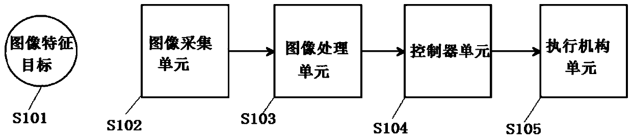
[0027] refer to figure 1 , an X-ray protective device with image recognition target tracking, comprising an image feature target (S101), an image acquisition unit (S102), an image processing unit (S103), a controller unit (S104), and an actuator unit (S105); the image acquisition unit (S102) is electrically connected to the image processing unit (S103); the image processing unit (S103) is electrically connected to the controller unit (S104); the controller unit (S104 ) is electrically connected with the actuator unit (S105).

[0028] The image acquisition unit (S102) transmits image data to the image processing unit (S103) in real time, and when the image processing unit (S103) recognizes that the image characteristic object (S101) appears, the coordinate data of the image characteristic object (S101) is transmitted Give the controller unit (S104) further processing; then the controller unit (S104) sends the corresponding control instruction to the actuator unit (S105) for mo...

Embodiment 2

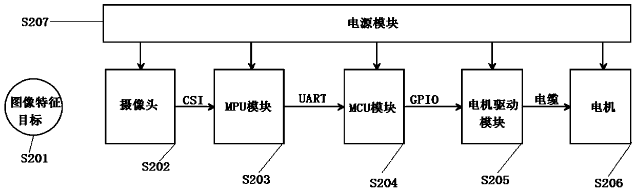
[0030] refer to figure 2 , an X-ray protection device with image recognition target tracking, comprising an image feature target (S201), a camera (S202), an MPU module (S203), an MCU module (S204), and a motor drive module (S205) . A motor (S206) and a power module (S207).

[0031] The camera (S202) is connected to the MPU module (S203) through a CSI interface, and transmits image data in real time to the MPU module (S203) for processing.

[0032] The MPU module (S203) is connected with the MCU module (S204) through a UART interface, and transmits the coordinate position data of the image feature target (S201) to the MCU module (S204) for processing in real time.

[0033] The MCU module (S204) is connected to the motor drive module (S205) through a GPIO interface, and transmits control instructions in real time to the motor drive module (S205) for execution.

[0034] The motor drive module (S205) is connected to the motor (S206) through a cable, and converts the control com...


PUM


Abstract

The invention discloses X-ray protection equipment with an image recognition target tracking function. The X-ray protection equipment comprises an image feature target, an image acquisition unit, an image processing unit, a controller unit and an actuating mechanism unit. The image acquisition unit is electrically connected with the image processing unit and transmits image data to the image processing unit for processing. The image processing unit is connected with the controller unit and transmits the identified image feature target coordinate data to the controller unit for processing. Thecontroller unit is connected with the actuating mechanism unit and transmits a control instruction to the actuating mechanism unit for moving operation. According to the X-ray protection equipment, asensor module does not need to be additionally arranged outside the equipment, and the equipment is more convenient to arrange; a sensor module does not need to be added outside the machine, so that the corresponding cost is saved; and a sensor module does not need to be additionally arranged outside the machine, so that wired or wireless data transmission with external equipment is not needed, and the system complexity is reduced.

Description

technical field [0001] The invention relates to the technical field of image recognition and X-ray protective equipment, in particular to an X-ray protective equipment with image recognition target tracking. Background technique [0002] X-ray protective equipment is mainly used in the DR room of the radiology department of the hospital to protect other parts of the patient that do not need to be photographed from X-ray exposure when the DR room of the radiology department of the hospital takes pictures; when the patient is taking pictures, the DR machine will move according to the photographed parts. [0003] At present, the X-ray protection equipment for automatic tracking of DR machines mainly uses laser ranging sensors or rope sensors to detect the movement of DR machines, and the X-ray protection equipment then moves the lead plate to the corresponding position for blocking. Both the laser ranging sensor and the pull rope sensor need to add an additional sensor module o...

Claims


Application Information

Patent Timeline
Patent Type & Authority Applications(China)
IPC IPC(8): A61B6/10
CPCA61B6/107
Inventor 李猛宋维东孙博
Owner NEURON INFORMATION TECH SHENZHEN CO LTD
Why Eureka
Try Eureka