
Medical cotton ball storage tank with cotton ball extruding and wetting mechanism

A technology for storing cans and cotton balls, applied in the field of machinery, can solve the problems of waste of disinfectant, unfavorable full use of disinfectant, etc., and achieve the effects of improving the wetting effect, reducing the amount of volatilization, and facilitating convergence

Active Publication Date: 2020-04-10
FUDAN UNIV SHANGHAI CANCER CENT
View PDF11 Cites 1 Cited by
  • Summary
  • Abstract
  • Description
  • Claims
  • Application Information

AI Technical Summary

Problems solved by technology

This method has the problem of wasting disinfectant solution. A 500mL bottle of povidone-iodine costs about 40-50 yuan in the market. Using this method, one bottle is replaced every two days on average.
Moreover, the existing cylinder for storing cotton balls has a flat bottom, which is not conducive to ensuring the full use of disinfectant

Method used


Image

  • Medical cotton ball storage tank with cotton ball extruding and wetting mechanism
  • Medical cotton ball storage tank with cotton ball extruding and wetting mechanism
  • Medical cotton ball storage tank with cotton ball extruding and wetting mechanism

Examples


specific Embodiment 1

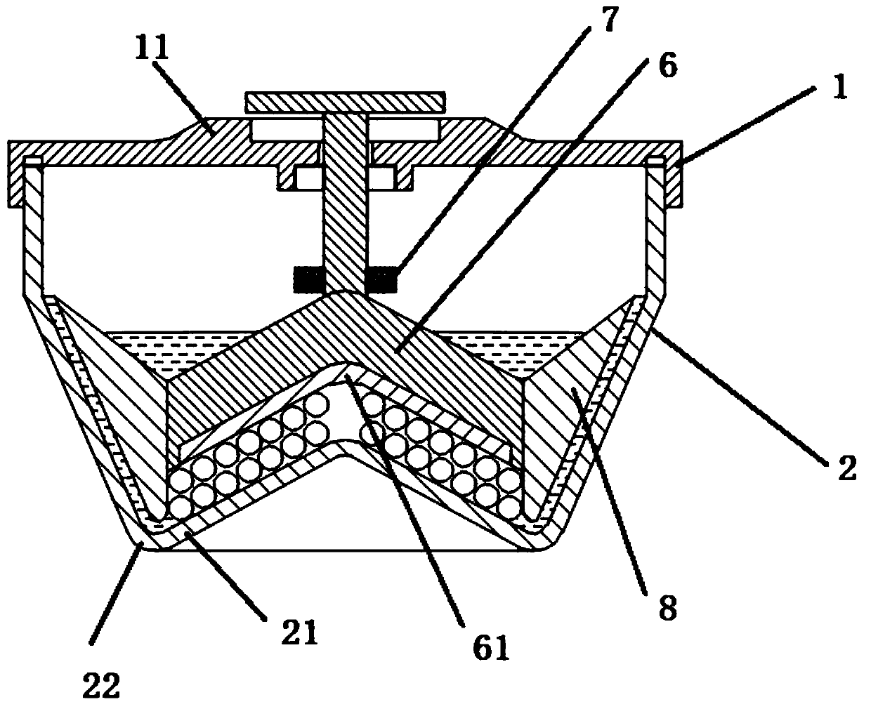
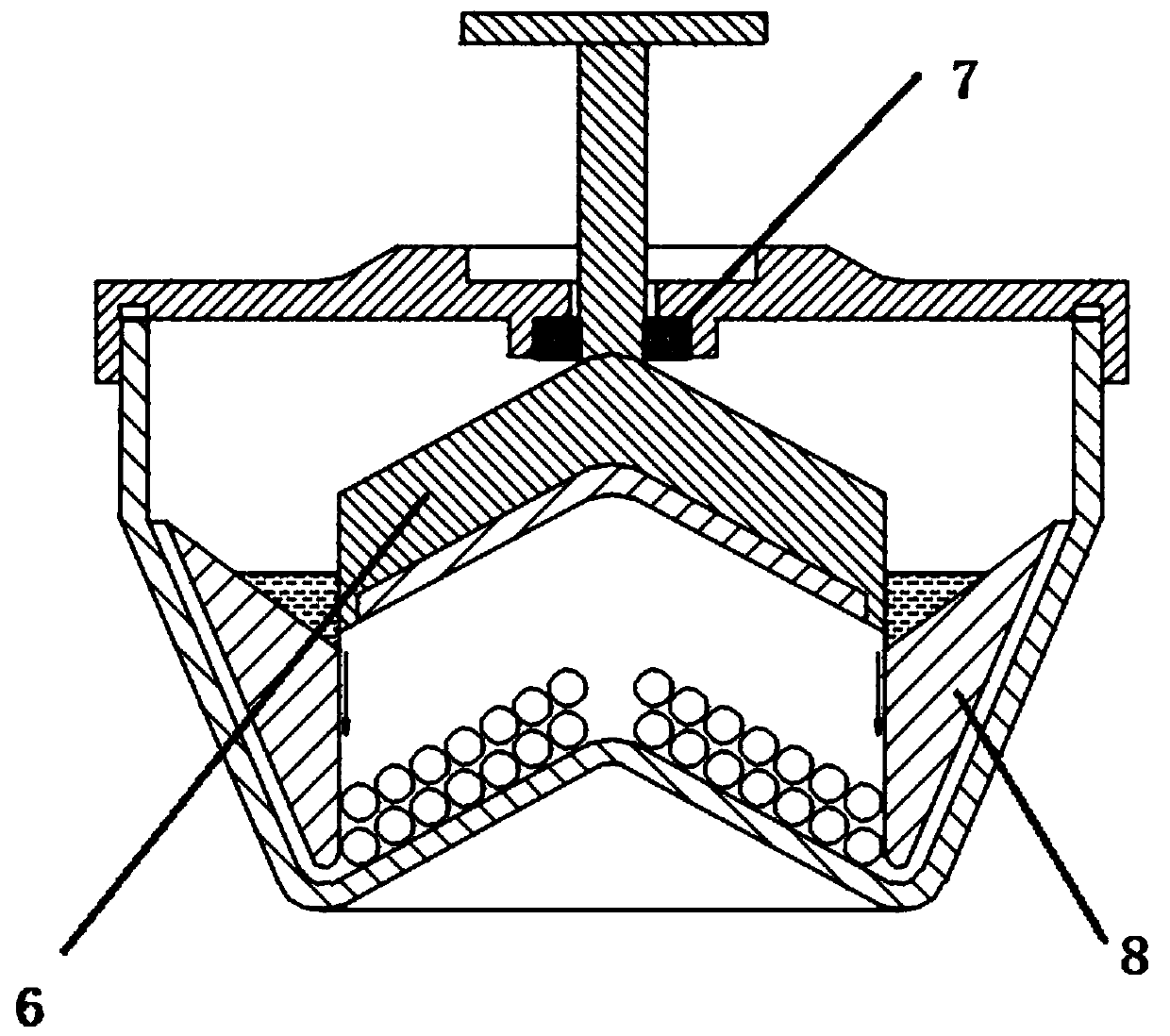
[0046] Specific embodiment 1, see figure 1 as well as figure 2 , a medical cotton ball storage tank with a cotton ball extrusion wetting mechanism, including a tank 2 for storing cotton balls and a tank cover 1, the tank 2 is threaded with the tank cover 1, and the connection between the tank 2 and the tank cover 1 A sealing ring 3 is provided at the place.

[0047] The jar 2 comprises a bottom plate 21 and a side plate, the bottom plate 21 and the side plate are connected by an arc-shaped transition portion 22 to form the jar 2, the bottom plate 21 is a conical bottom plate 21 increasing from top to bottom, the bottom plate 21, the arc-shaped transition portion 22 and The side plates are connected to form a V-shaped annular groove in cross-section, and the annular groove is used as a placement groove for placing cotton balls, and the installation groove is connected with the sealing member by interference fit.

[0048] An annular inner plate 8 is installed in the tank body...

specific Embodiment 2

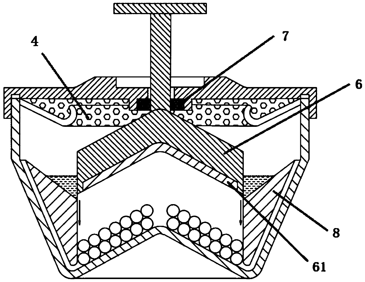
[0057] Specific embodiment 2, see image 3 , on the basis of specific embodiment 1, the side plate includes an upper part and a lower part arranged up and down, the inner diameter of the upper part is equal up and down, and the inner diameter of the lower part decreases from top to bottom; a drain board 4 is connected to the inner side of the top of the top; The vertical projection of the inside is outside the vertical projection of the inner wall of the inner panel 8 . It is convenient for tweezers to take the cotton ball between the inner board 8 and the base board 21. Drain board 4 does not cause disturbance. The draining plate 4 includes a mesh plate inclined downward from the outside to the inside and an arc-shaped upward flange; mesh holes are also opened on the flange. It is convenient to hold the cotton ball with tweezers in hand, and squeeze the drain plate 4 to drain. When a spring is also installed between the piston and the tank cover, the piston is positioned a...

specific Embodiment 3

[0058] Specific embodiment 3, see Figure 4 , on the basis of the specific embodiment 1 or 2, the center of the bottom plate 21 is equipped with a hollow tube with a lower end seal, and the hollow tube is a liquid storage tube 5 for putting in physiological saline; For the cavity where the cotton ball is placed, the inner cavity of the hollow tube communicates with the cavity. By adding the design of the hollow tube, it is convenient to realize the effect of humidifying and moisturizing in the cavity. Further reduce the amount of volatility. The upper end of the liquid storage tube 5 is higher than the highest point of the top plate; the center of the piston 6 is provided with a gap for inserting the liquid storage tube 5 protruding from the top plate area. It is convenient for the liquid storage tube 5 not to interfere with the descending of the piston 6 . A groove is provided at the lower end of the piston 6, and a pressing plate 61 is fixed in the groove. It is convenie...


PUM


Abstract

The invention relates to the technical field of machinery. The invention discloses a medical cotton ball storage tank with a cotton ball extruding and wetting mechanism. The medical cotton ball storage tank comprises a tank and a tank cover; the tank comprises a bottom plate and a side plate; the bottom plate and the side plate are connected through an arc-shaped transition part to form the tank;the bottom plate is a conical bottom plate which gradually expands from top to bottom; an annular inner side plate is arranged in the tank body; the inner side plate divides an inner cavity of the tank body into a main chamber and a flow guide chamber which are arranged inside and outside; the flow guide chamber is defined by the inner side plate and the side plate; and a gap is reserved between the bottom of the inner side plate and the inner wall of the tank body. The medical cotton ball storage tank also comprises a cotton ball extruding and wetting mechanism; the cotton ball extruding andwetting mechanism comprises a piston and a handle for driving the piston to slide up and down; a through hole for the handle to pass through is formed in the tank cover; the outer side wall of the piston is in interference fit with the inner wall of the inner side plate; a groove matched with the top plate is formed in the bottom of the piston; and the top of the piston is in a conical shape witha narrow upper part and a wide lower part. The medical cotton ball storage tank can ensure that cotton balls at the edge of upper-layer are in a wetting state.

Description

technical field [0001] The invention relates to the technical field of machinery, in particular to a storage device for medical cotton balls. Background technique [0002] In clinical departments, dressings should be frequently changed and disinfected for patients after surgery, so as to observe wound healing and control wound infection. In actual clinical application, medical staff generally use iron cylinders to manufacture and store sterile cotton balls. [0003] Under normal circumstances, medical staff put sterile cotton balls into the iron tank, then pour alcohol or povidone-iodine, use sterile forceps to fully soak the cotton balls, and leave them for later use. During use, the medical staff uses sterile tweezers to clip the cotton ball, put it in the dressing changing bowl, and then wipe the wound for the patient. [0004] However, due to the lack of airtightness in the cylinder used for storing cotton balls, disinfectants such as alcohol and povidone-iodine will e...

Claims


Application Information

Patent Timeline
IPC IPC(8): A61M35/00A61J1/00
CPCA61J1/00A61M35/00
Inventor 宋振宇宋佃海
Owner FUDAN UNIV SHANGHAI CANCER CENT
Learn More