Linkage type magnetic separation device for rare earth permanent magnet material

A rare earth permanent magnet and magnetic separation device technology, which is applied in magnetic separation, solid separation, grain processing, etc., can solve the problems of time-consuming, labor-intensive, waste of rare earth resources, etc., and achieve the effect of reducing the unit volume

Inactive Publication Date: 2020-04-10
安徽延创通讯科技有限公司
View PDF0 Cites 4 Cited by
  • Summary
  • Abstract
  • Description
  • Claims
  • Application Information

AI Technical Summary

Problems solved by technology

[0007] In the process of producing rare earth permanent magnet materials, impurities such as crucible erosion and falling off, wood chips, copper chips and other impurities are easily mixed in, resulting in the problem of low quality of finished products. If these finished products are directly discarded, it is obviously a huge waste of rare earth resources
However, in the existing technology, most of them are recycled manually, which is time-consuming, labor-intensive, and the recycling efficiency is not high.

Method used


Image

  • Linkage type magnetic separation device for rare earth permanent magnet material
  • Linkage type magnetic separation device for rare earth permanent magnet material
  • Linkage type magnetic separation device for rare earth permanent magnet material

Examples


Embodiment 1

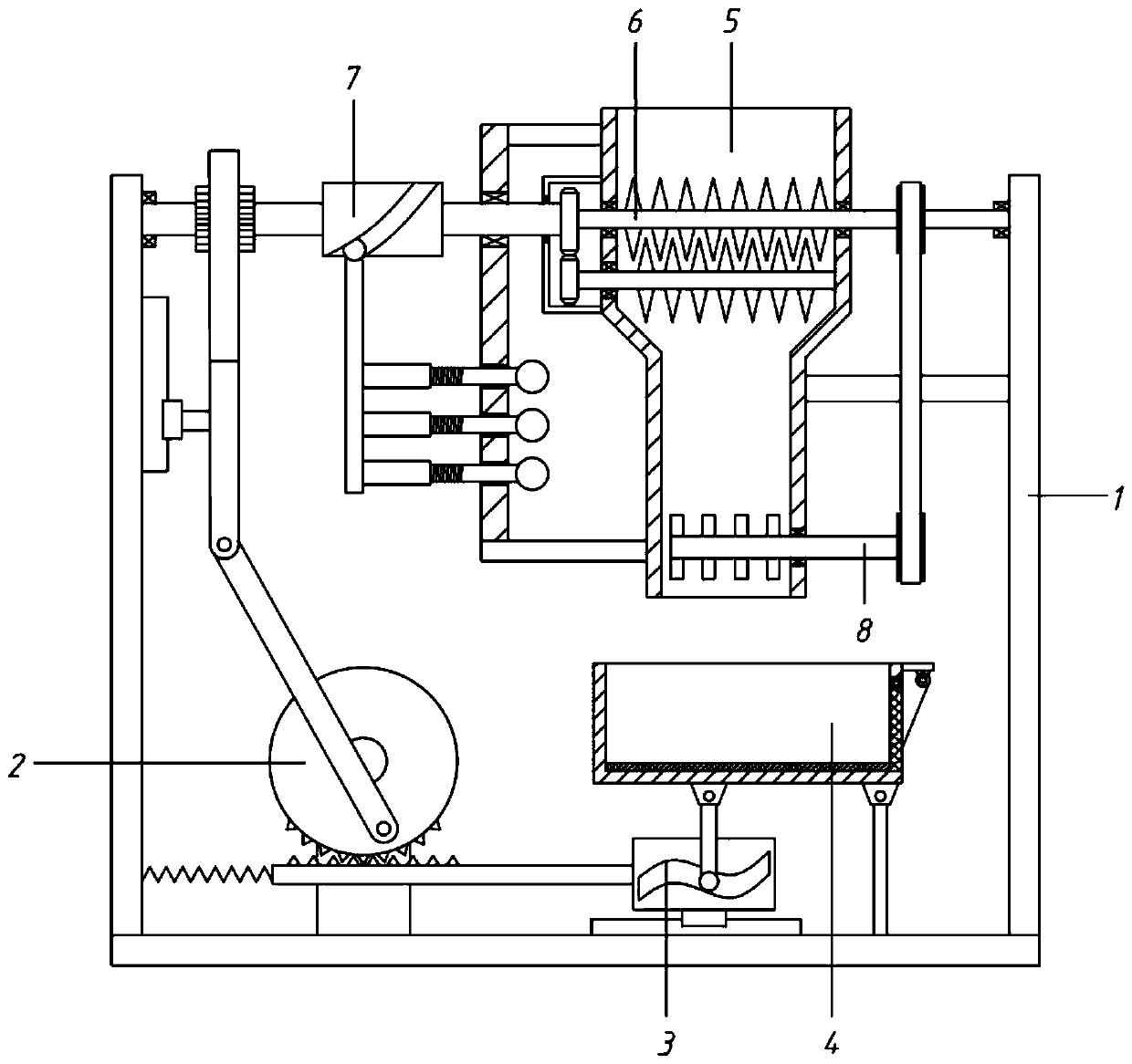
[0058] A linkage type magnetic separation device for rare earth permanent magnet materials, comprising a frame 1, a drive assembly 2, a housing 5, a crushing assembly 6, a shaking assembly 3 and a magnetic separation box 4;

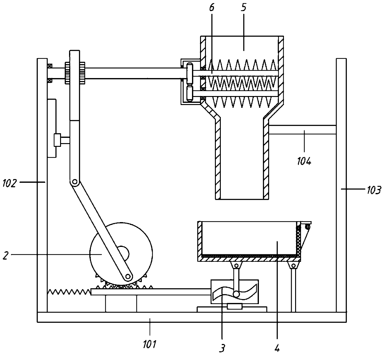
[0059] The frame 1 includes a base 101, a left side plate 102 and a right side plate 103 arranged at the left and right ends of the base 101;

[0060] The driving assembly 2 is arranged on the left part of the base 101; the housing 5 is arranged above the right part of the base 101, and is fixedly connected to the left side of the right side plate 103 through the support frame 104; the housing 5 is divided into an upper crushing chamber 501 and a lower feeding chamber. Cavity 502; crushing chamber 501 is provided with a crushing assembly 6; the magnetic separation box 4 is arranged below the housing 5, and the bottom of the magnetic separation box 4 is provided with a shaking assembly 3; the driving assembly 2 drives the crushing assembly 6 and the shaking...

Embodiment 2

[0062] A linkage type magnetic separation device for rare earth permanent magnet materials, comprising a frame 1, a drive assembly 2, a housing 5, a crushing assembly 6, a shaking assembly 3 and a magnetic separation box 4;

[0063] The frame 1 includes a base 101, a left side plate 102 and a right side plate 103 arranged at the left and right ends of the base 101;

[0064] The driving assembly 2 is arranged on the left part of the base 101; the housing 5 is arranged above the right part of the base 101, and is fixedly connected to the left side of the right side plate 103 through the support frame 104; the housing 5 is divided into an upper crushing chamber 501 and a lower feeding chamber. Cavity 502; crushing chamber 501 is provided with a crushing assembly 6; the magnetic separation box 4 is arranged below the housing 5, and the bottom of the magnetic separation box 4 is provided with a shaking assembly 3; the driving assembly 2 drives the crushing assembly 6 and the shaking...

Embodiment 3

[0077] On the basis of embodiment 2,

[0078] A vibration material assembly 7 is also provided; the vibration material assembly 7 includes a support plate 701, a cylindrical cam 702, a roller 703, a third rod 704, a fourth rod 705 and a collision end 706;

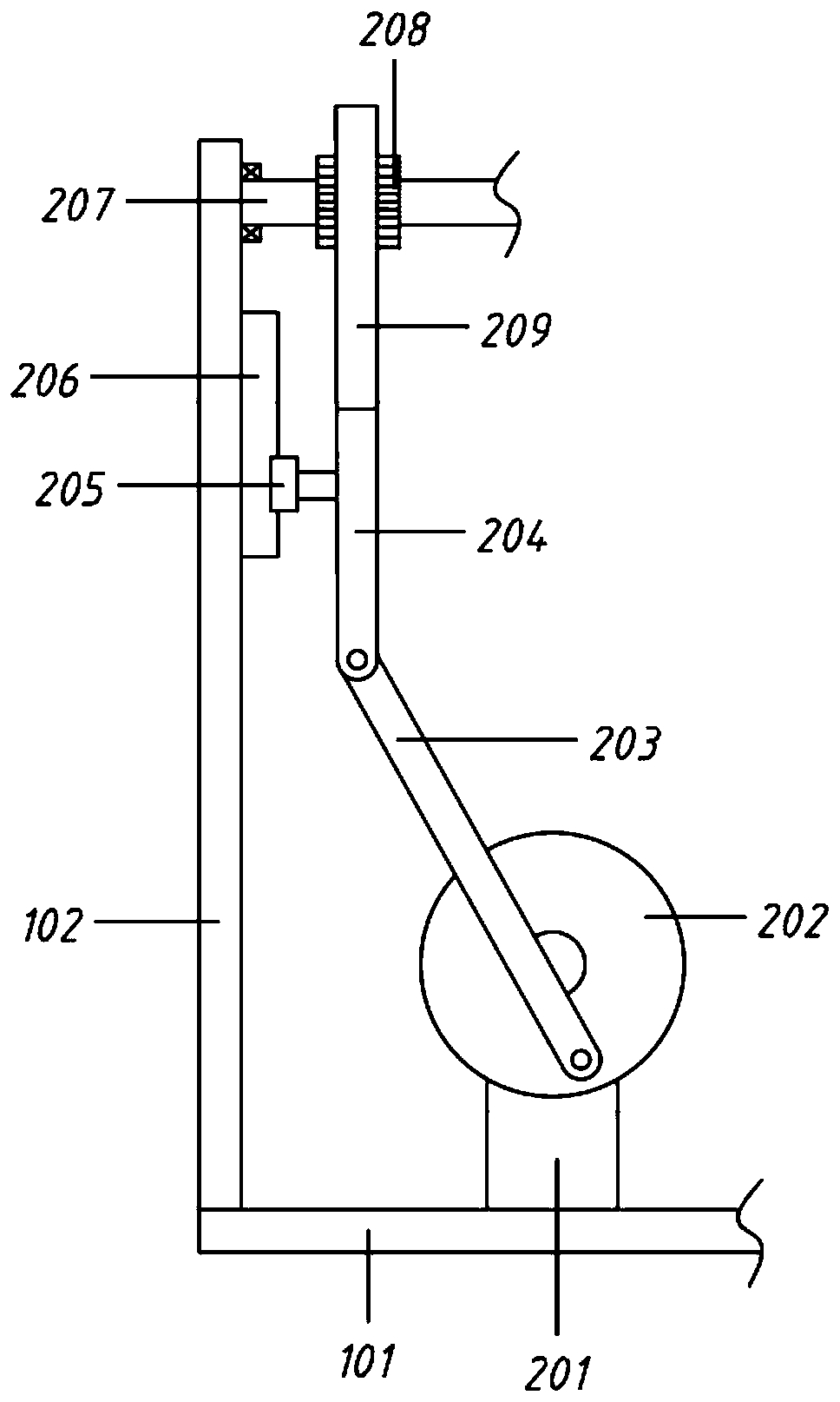
[0079] The left side of the housing 5 is provided with a support plate 701, the upper and lower ends of the support plate 701 are bent to the right and fixedly connected to the housing 5; the first rotating shaft 206 passes through and rotates to connect with the supporting plate 701; the first rotating shaft 206 is equipped with a cylindrical cam 702 , the cylindrical cam 702 is arranged on the left side of the support plate 701; the cylindrical cam 702 is matched with a roller 703, and the roller 703 is connected downward with the third rod 704, and the third rod 704 is connected with the fourth rod 705 to the right, and the fourth rod 705 wears Through the support plate 701 and equipped with a collision end 706.

[0080...


PUM


Abstract

The invention relates to the technical field of magnetic separation equipment for rare earth permanent magnet materials, in particular to a linkage type magnetic separation device for a rare earth permanent magnet material. A servo motor is adopted for driving a rotary table to rotate, a first rod rotates along with the rotary table to drive a second rod to move up and down, and a first rack movesrelative to a first gear and drives the first gear to rotate, so that a first rotary shaft rotates to serve as power input of a smashing assembly to smash materials fed from the top. In addition, intermittent cooperation of the gear and a second rack is not completed while rotation of the rotary table, deformation of a spring is matched to drive a moving block to move left and right, a connectingrod is moved up and down through the action of an S-shaped hole and a sliding shaft, so that the left part of a magnetic separation box ascends and descends, and finally, the magnetic separation boxshakes to make materials shake and make full contact with an electromagnetic chuck, and therefore, the magnetic separation effect is guaranteed, and the magnetic separation efficiency is improved.

Description

technical field [0001] The invention relates to the technical field of magnetic separation equipment for rare earth permanent magnet materials, in particular to a linkage type magnetic separation device for rare earth permanent magnet materials. Background technique [0002] Rare earth permanent magnet materials, that is, permanent magnet materials contain rare earth metals as alloying elements. Permanent magnet material refers to the ability to maintain strong magnetism for a long time after magnetization and removal of the external magnetic field. [0003] Rare earth permanent magnet material is an alloy composed of samarium, neodymium mixed rare earth metals and transition metals (such as cobalt, iron, etc.), which is pressed and sintered by powder metallurgy, and magnetized by a magnetic field. [0004] Rare earth permanent magnets are divided into: samarium cobalt (SmCo) permanent magnets and neodymium iron boron (NdFeB) permanent magnets. Among them, the magnetic ene...

Claims


Application Information

Patent Timeline
Patent Type & Authority Applications(China)
IPC IPC(8): B02C18/14B02C18/24B02C18/16B02C18/22B02C23/08B03C1/02
CPCB02C18/14B02C18/16B02C18/2216B02C18/24B02C23/08B03C1/02
Inventor 王雅婷
Owner 安徽延创通讯科技有限公司
Why Eureka
Try Eureka