Hollow layer forming method and multi-hollow-layer thermal barrier pipe

A hollow, thermal barrier technology, applied in the field of pipe hydroforming, can solve the problems of high technical difficulty, cumbersome process and high technical requirements for water injection holes

Active Publication Date: 2020-04-10
WEIFANG BELEAD AUTOMOBILE PARTS
View PDF8 Cites 0 Cited by
  • Summary
  • Abstract
  • Description
  • Claims
  • Application Information

AI Technical Summary

Problems solved by technology

[0005] However, the technical requirements for the opening of the water injection hole in this manufacturing process are high, the inner tube is opened and the outer tube is blocked; the usual method is to first drill the two-layer tube through the hole, and then repair and seal the hole in the outer tub

Method used


Image

  • Hollow layer forming method and multi-hollow-layer thermal barrier pipe
  • Hollow layer forming method and multi-hollow-layer thermal barrier pipe
  • Hollow layer forming method and multi-hollow-layer thermal barrier pipe

Examples


Embodiment 1

[0053] Embodiment one: forming as Figure 8 The shown single hollow layer pipe body comprises the following steps:

[0054] S1 blanking

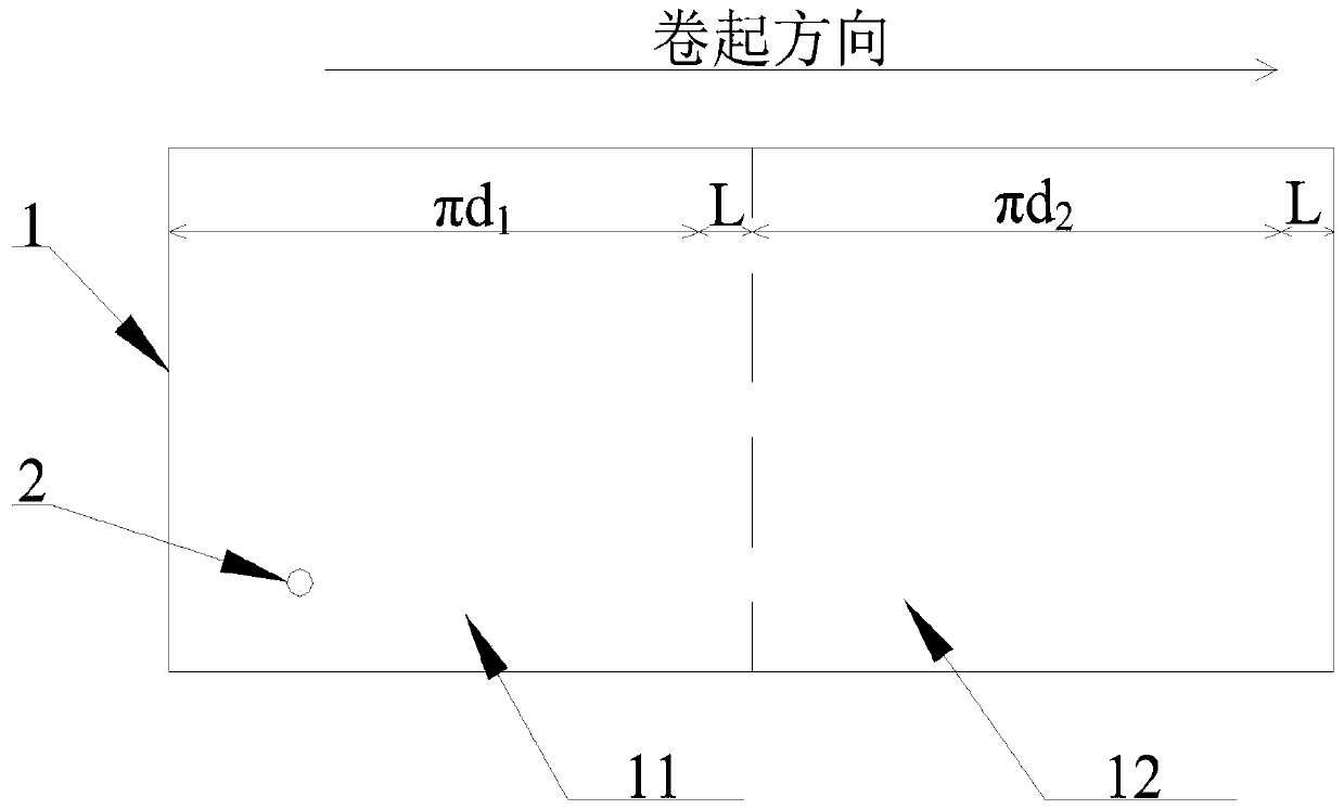
[0055] see figure 1 , preparing a plate 1 of a predetermined size; opening a first water injection hole 2 at a predetermined position;

[0056] combine Figure 5 , the structure of the single hollow-layer pipe body before forming includes the first layer of pipe 3 (diameter is d 1 ) and the second layer of pipe 31 (diameter is d2 ); the forming of each layer of tubes requires an overlapping area of ​​width L, so the plate 1 includes a first zone 11 and a second zone 12 . The length of the first zone 11 is πd 1 +L; the length of the second zone 12 is πd 2 +L. The minimum length of the board 1 along the rolling direction is the sum of the lengths of the first zone 11 and the second zone 12 . Those skilled in the art can properly enlarge the length of the board 1 according to the safety of the process, so as to avoid material shortage c...

Embodiment 2

[0069] Embodiment two: forming such as Figure 14 The shown pipe body with two hollow layers comprises the following steps:

[0070] S1 blanking

[0071] see Figure 9 , prepare a plate 1 with a predetermined size; open a first water injection hole 2 and two first through holes 211 at a predetermined position; the centers of the two first through holes 211 are located on the same straight line parallel to the rolling direction.

[0072] combine Figure 11 , the structure of the pipe body with two hollow layers before molding includes the first layer of pipe 3 (diameter is d 1 ), the second layer of pipe 31 (diameter is d 2 ) and the third layer of pipe 32 (diameter is d 3 ).

[0073] Therefore, when blanking, the plate 1 includes a first zone 11 , a second zone 12 and a third zone 13 . The length of the first zone 11 is πd 1 +L; the length of the second zone 12 is πd 2 +L; the length of the third zone 13 is πd 3 +L.

[0074] Two first through holes 211 are opened in...

Embodiment 3

[0084] Embodiment three: forming a pipe body with three hollow layers, comprising the following steps:

[0085] S1 blanking

[0086] As mentioned above, the pipe body with three hollow layers needs to have four layers of pipes before forming, namely the first layer of pipes 3 , the second layer of pipes 31 , the third layer of pipes 32 and the fourth layer of pipes 33 .

[0087] Therefore, see Figure 15 , the board 1 includes a first zone 11 , a second zone 12 , a third zone 13 and a fourth zone 14 . The length of the first zone 11 is πd 1 +L; the length of the second zone 12 is πd 2 +L; the length of the third zone 13 is πd 3 +L; the length of the fourth zone 14 is πd 4 +L.

[0088] Open the first water injection hole 2 and two first through holes 211 as in the second embodiment at the predetermined position of the plate 1; open a second through hole 221 in the first area 11, the second area 12 and the third area 1 respectively ; The centers of the three second throug...


PUM

PropertyMeasurementUnit
Thicknessaaaaaaaaaa

Abstract

The invention relates to the technical field of pipe hydraulic forming, and provides a hollow layer forming process. The process comprises the following steps: S1, performing blanking: preparing a plate with a preset size specification for rolling and plate rolling forming, and forming n through hole groups; S2, preparing a pipe blank: rolling the plate to sequentially form pipes from the first layer to the (n + 1)-th layer; S3, forming the hollow layer by adopting an internal high-pressure mode. In this way, multiple through holes are formed in the plate in advance, and then the plate is rolled into the pipe blank with the multi-layer pipe; a pre-bulging process in the prior art is replaced, so the development and manufacturing of a pre-bulging die are omitted, and the die development andprocess cost is saved. A hole patching procedure is omitted, so the forming difficulty of the water injection hole is greatly reduced; meanwhile, a plurality of groups of through holes can be formedin advance, and a plurality of water injection holes are formed after rolling, so the formation of a plurality of hollow layers is realized, and the blank of the prior art is filled. The invention provides a multi-hollow-layer thermal barrier pipe. The multi-hollow-layer thermal barrier pipe is provided with a plurality of hollow layers.

Description

technical field [0001] The invention belongs to the technical field of pipe hydraulic forming, and in particular relates to a hollow layer forming method. Background technique [0002] With the improvement of environmental protection requirements, the emission standards of automobile exhaust are becoming more and more stringent. In order to make the exhaust gas meet the standard, the exhaust gas is usually discharged after catalytic reaction in the exhaust pipe. In order for the exhaust gas to fully react, it needs to reach a certain temperature, so the insulation performance of the exhaust pipe is very important for the exhaust gas treatment. [0003] The commonly used insulation method for the exhaust pipe is to wrap the outer layer of the metal pipe with insulation cotton. However, this method has poor thermal insulation ability, which seriously affects the reaction effect of automobile exhaust and catalyst; at the same time, the overall rigidity of the pipe body is low...

Claims


Application Information

Patent Timeline
IPC IPC(8): B21C37/09B21D26/033B21D26/045B21D26/047B21D26/049
CPCB21C37/09B21D26/033B21D26/045B21D26/047B21D26/049
Inventor 王景晓高林玉胡家磊王凯何海林易斌
Owner WEIFANG BELEAD AUTOMOBILE PARTS
Why Eureka
Try Eureka