Multi-station numerical control lathe

A numerical control lathe and multi-station technology, applied in the field of numerical control lathes, can solve the problems of difficult control of the starting position of processing, unfavorable adjustment of the lateral position, damage to the structure of the machine tool, etc., achieving the effect of easy operation of the structure, speeding up the maintenance rate, and optimizing the structure.

Active Publication Date: 2020-04-10
TONGLING ZHAOLIN IND & TRADE CO LTD
View PDF7 Cites 4 Cited by
  • Summary
  • Abstract
  • Description
  • Claims
  • Application Information

AI Technical Summary

Problems solved by technology

[0004] In order to make up for the shortcomings of the existing technology, it is difficult to control the starting position of the processing when the existing machine tools are processed, it is not conducive to adjusting the lateral position and it is easy to make mistakes when adjusting the cutting depth, which will cause damage to the processing wheel and the structure of the existing machine tools is relatively complicated. Not only the operation Complicated and difficult to maintain, the present invention proposes a multi-station CNC lathe

Method used


Image

  • Multi-station numerical control lathe
  • Multi-station numerical control lathe
  • Multi-station numerical control lathe

Examples


Embodiment approach

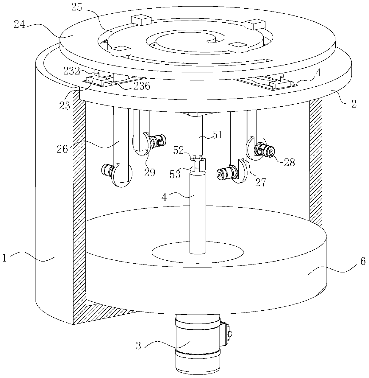
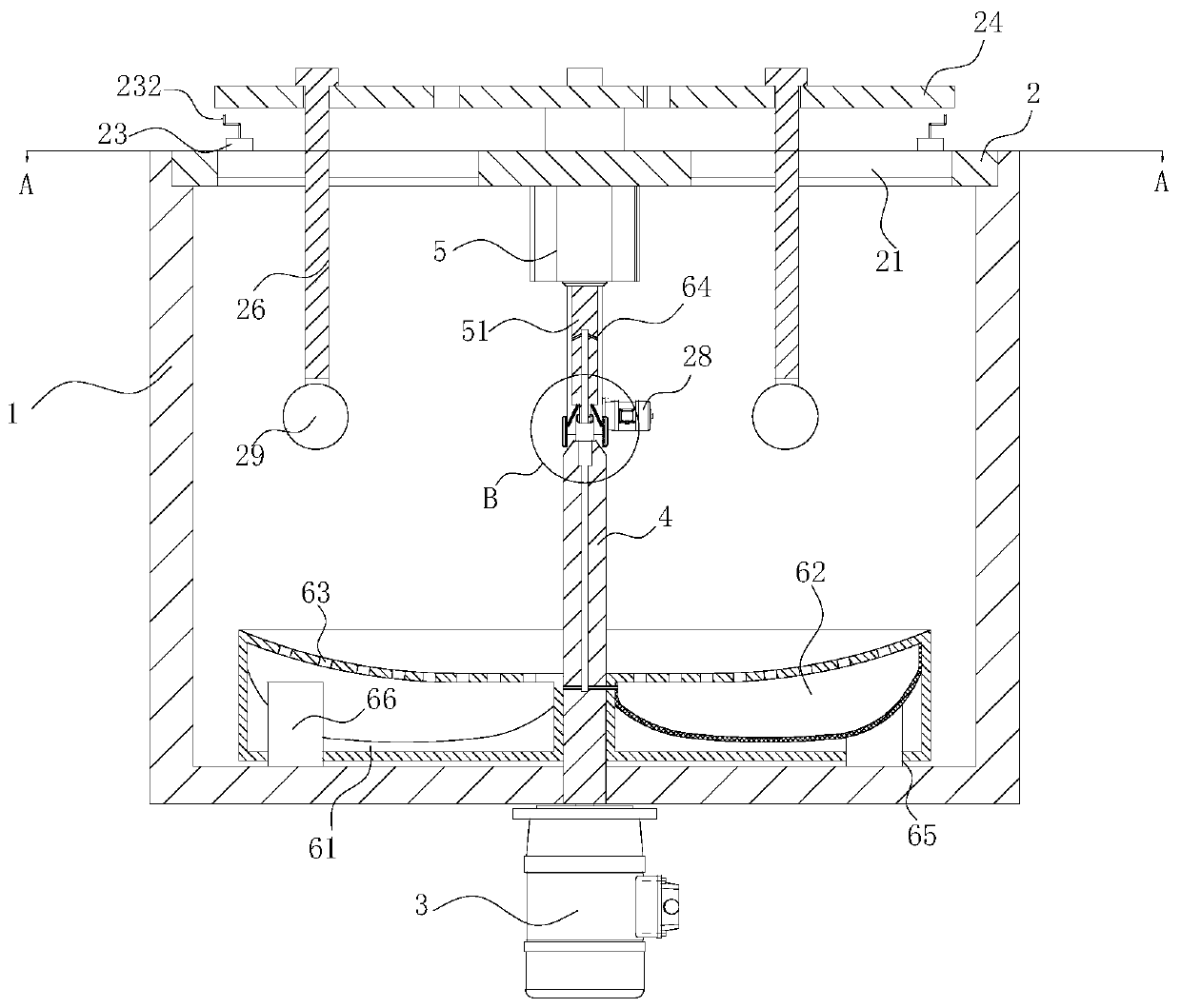
[0026] As an embodiment of the present invention, the fixed cover 2 is fixedly connected with a cylinder 5 on the side surface close to the housing 1; One end of the telescopic shaft 51 is hinged with a support plate 53; the opposite end of the telescopic shaft 51 and the support shaft 4 is designed in a truncated cone shape; during work, the workpiece to be processed is placed on the support shaft 4, and the fixed cover 2 is closed to control the expansion and contraction of the cylinder 5. , so that the telescopic rod moves toward the support shaft 4, the support plate 53 slides on the side of the truncated cone of the support shaft 4, and the rotation of the support rod 52 makes the support plate 53 play a role in fixing the workpiece to be processed, and simultaneously starts the first motor 3 , the first motor 3 drives the support shaft 4 to rotate, and the support plate 53 and the support shaft 4 are fixed at the same time to be processed, which can effectively avoid the ...


PUM


Abstract

The invention belongs to the technical field of numerical control lathes, and particularly relates to a multi-station numerical control lathe. The multi-station numerical control lathe comprises a shell, a fixed cover and a first motor. The first motor is mounted below the shell, and a first motor rotating shaft penetrates through the shell. The portion, in a shell inner cavity, of the first motorrotating shaft is fixedly connected with a support shaft. The maximum ends of first sliding grooves are elastically connected with wave plates through springs. Fixing blocks are mounted in the firstsliding grooves correspondingly. The portion, located in fixing block inner cavities, of the rotating shaft is fixedly connected with a rotating disc. Two hinge rods are hinged to the rotating disc. Asliding rod is hinged to the other end of each hinged rod, and the sliding rods penetrate through the fixing blocks in design. The ends, located at the outer sides of the fixing blocks, of the sliding rods are fixedly connected with fixing plates. According to the multi-station numerical control lathe, by arranging the fixing blocks, the wave plates and limiting grooves, moving rods can be defined from multiple aspects, so that processing wheels can accurately and rapidly cut the surface of a workpiece to be machined, and the arrangement of the four processing wheels greatly improves the working efficiency.

Description

technical field [0001] The invention belongs to the technical field of numerically controlled lathes, in particular to a multi-station numerically controlled lathe. Background technique [0002] CNC machine tool is the abbreviation of numerical control machine tool, which is an automatic machine tool equipped with a program control system. The control system can logically process programs with control codes or other symbolic instructions, decode them, express them in coded numbers, and input them into the numerical control device through the information carrier. After calculation and processing, various control signals are sent by the numerical control device to control the movement of the machine tool, and the parts are automatically processed according to the shape and size required by the drawing. CNC machine tools solve complex, precise, small-batch, and multi-variety parts processing problems. It is a flexible, high-efficiency automatic machine tool that represents the...

Claims


Application Information

Patent Timeline
Patent Type & Authority Applications(China)
IPC IPC(8): B23B7/12B23B25/06B23Q11/10
CPCB23B7/12B23B25/06B23Q11/10
Inventor 卢兆林卢小升卢云霞
Owner TONGLING ZHAOLIN IND & TRADE CO LTD
Why Eureka
Try Eureka