
Blind hole machining rotary cutting system and blind hole machining method

A processing method, blind hole technology, applied in metal processing equipment, manufacturing tools, welding/welding/cutting items, etc., can solve the problems of large blind hole taper, high cost of rotary cutting equipment, etc.

Active Publication Date: 2020-04-10
WUHAN HGLASER ENG CO LTD
View PDF12 Cites 2 Cited by
  • Summary
  • Abstract
  • Description
  • Claims
  • Application Information

AI Technical Summary

Problems solved by technology

[0008] The purpose of the present invention is to provide a blind hole processing rotary cutting system and a blind hole processing method to solve the problems in the prior art that the blind hole taper of the non-transparent and brittle material processing is relatively large and the processing rotary cutting equipment is expensive. technical issues

Method used


Image

  • Blind hole machining rotary cutting system and blind hole machining method
  • Blind hole machining rotary cutting system and blind hole machining method
  • Blind hole machining rotary cutting system and blind hole machining method

Examples


Embodiment

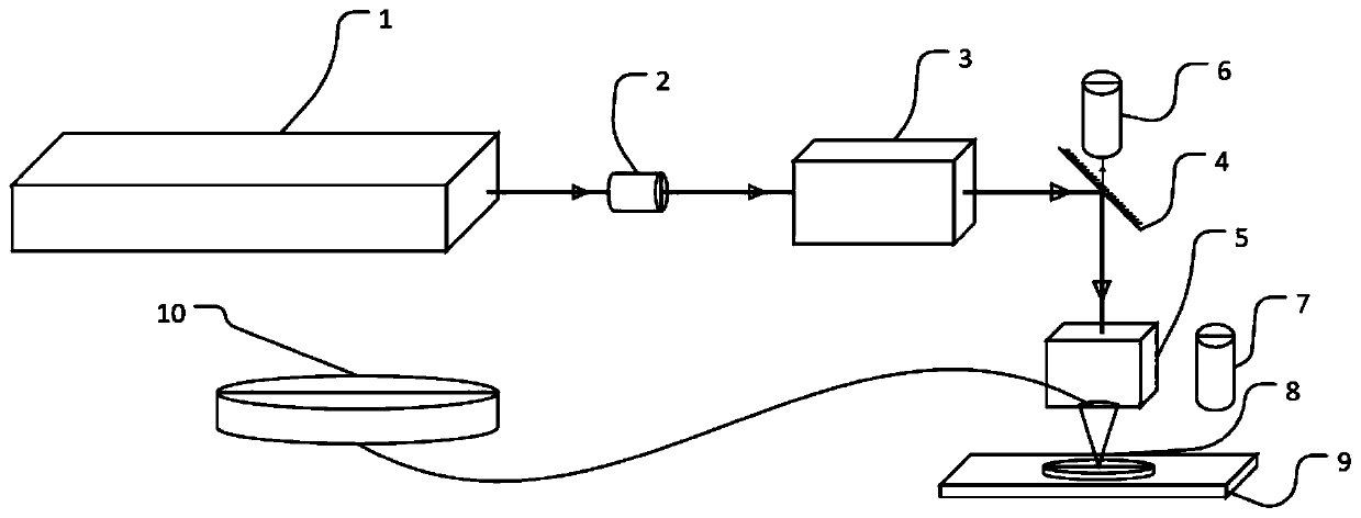
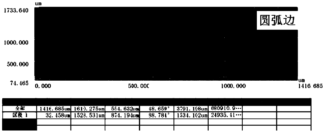
[0055] Please refer to figure 1 , this embodiment provides a blind hole processing rotary cutting system, figure 1 Schematic diagram of the structure of the rotary cutting system for blind hole processing provided by the embodiment of the present invention; figure 2 The magnified effect diagram of the blind hole processed by the blind hole processing rotary cutting system provided for the embodiment of the present invention, from left to right is the blind hole effect diagram enlarged by 50 times, the blind hole edge effect diagram enlarged by 225 times, and the blind hole edge effect diagram enlarged by 225 times Blind hole corner renderings. Figure 3-Figure 5 The 3D microscope measurement results of the blind holes processed by the blind hole processing rotary cutting system provided for the embodiments of the present invention.

[0056] The blind hole processing rotary cutting system provided in this embodiment is an ultra-fast laser drilling processing equipment, which...


PUM


Abstract

The invention discloses a blind hole machining rotary cutting system and a blind hole machining method, and relates to the field of machining. The blind hole machining rotary cutting system comprisesa laser device, a beam expander, a polarization device, a mirror lens, an angle adjusting device and a working platform used for loading a to-be-machined product, the laser of the laser device can sequentially pass through the beam expander, the polarization device, the mirror lens and the angle adjusting device to be irradiated on the working platform, the polarization device is used for changingthe linearly polarized light of the laser into circularly polarized light or radially polarized light, the mirror lens can change the laser propagation direction, and the angle adjusting device can change the angle of laser irradiation on the working platform. The blind hole machining method is suitable for the blind hole machining rotary cutting system. The blind hole machining rotary cutting system and the blind hole machining method are provided so as to solve the technical problems that in the prior art, the taper of a blind hole machined in a non-transparent brittle material is relatively large, and the cost of machining rotary cutting equipment is high to a certain extent.

Description

technical field [0001] The invention relates to the field of machining, in particular to a blind hole machining rotary cutting system and a blind hole machining method. Background technique [0002] Ceramics, especially non-transparent and brittle ceramics, are formed by sintering; the formed ceramics have many excellent properties in electricity, magnetism, sound, light, heat, etc., which are difficult for other materials to match. Therefore, it is widely used in energy development, electronic technology, sensing technology, laser technology, optoelectronic technology, infrared technology, biotechnology, environmental science and so on. [0003] Due to the wide range of ceramic applications, the simple sintering process can no longer meet the rich and colorful needs in terms of shape and structure; however, 3D printing is time-consuming and costly, and the physical properties of ceramic materials are relatively brittle, and mechanical processing is subject to certain restri...

Claims


Application Information

Patent Timeline
IPC IPC(8): B23K26/402B23K26/386B23K26/064B23K26/142
CPCB23K26/402B23K26/386B23K26/064B23K26/0643B23K26/142B23K2103/52
Inventor 王玉莹王雪辉刘彪杨立昆刘勇
Owner WUHAN HGLASER ENG CO LTD
Learn More