Tight winding equipment for RTP composite tubes

A composite pipe and equipment technology, which is applied in the field of composite pipe production equipment, can solve problems such as slippage and failure to meet RTP composite pipe transmission, and achieve the effect of avoiding slippage and high transmission efficiency

Inactive Publication Date: 2020-04-10
ANHUI JIELANTE NEW MATERIAL CO LTD
View PDF7 Cites 3 Cited by
  • Summary
  • Abstract
  • Description
  • Claims
  • Application Information

AI Technical Summary

Problems solved by technology

[0004] The object of the present invention is to provide a kind of tight winding equipment for RTP composite pipe, solve the following technical problems: (1) The connecting block is driven to slide on the waist-shaped hole on the convex strip through the piston rod of the telescopic cylinder, and the connecting block cooperates with the spring pin . The rotating pin drives the side connecting plate to move towards the RTP composite pipe, and then drives the three conveying tracks to contact the outer wall of the RTP composite pipe. The second motor drives the conveying crawler to rotate through the driving wheel, and the conveying crawler begins to convey the RTP composite pipe. The internal structure of the barrel is set so that the equipment can meet the transmission work of RTP composite pipes with different outer diameters. At the same time, the three conveyor belts contact and convey RTP composite pipes at the same time, effectively avoiding slipping during the transmission of RTP composite pipes. Retractable on both sides, so that the transmission efficiency of the RTP composite pipe is higher, solving the problem that the reinforcing fiber and filter belt winding equipment used for RTP composite pipes in the prior art cannot meet the transmission of RTP composite pipes with different outer diameters, and at the same time, slippage is prone to occur during the transmission process (2) The fourth motor output shaft drives the drive rod to rotate, and the drive rod drives the fastening cylinder to rotate, and the fastening cylinder unwinds the reinforced fiber and filter belt wound on it, and the reinforced fiber and filter belt are in RTP The surface of the composite tube is wound, and at the same time, the driving rod can actively unwind the reinforcing fiber and filter belt through the fastening tube, and there will be no jamming that occurs when the tube feeding tube passes through the reinforcing fiber and filter belt to drive the fastening tube to passively unwind. The output shaft of the third motor drives the translation plate to slide on the fixed frame through the screw rod and the nut, and then drives the fastening cylinder to translate, which can adjust the relative position of the fastening cylinder and the tube delivery cylinder, and solve the problem of reinforcing fiber and filter belt winding in the prior art The technical problem of easy knotting on the RTP composite pipe; (3) By pulling the outer baffle, the bottom of the outer baffle is flipped along the hexagonal plate, driving the cross bar to rotate, and then adjusting the angle between the outer baffle and the retractable cylinder , adjust the maximum outer diameter of the coiled tube, which can meet the needs of retracting and unwinding RTP composite tubes of different lengths and different outer diameters. After the coiled tube is completed, the cross-lifting frame drives the hexagonal plate to descend, and the hexagonal plate passes through the lifting port. The RTP composite pipe coiled on the outer baffle comes out from the top of the outer baffle, and the wound RTP composite pipe can be taken out, solving the problem of the length of the RTP composite pipe that can be wound by the reel when the RTP composite pipe is retracted in the prior art And the outer diameter is relatively fixed, which cannot meet the requirements of retracting and unwinding RTP composite pipes of different lengths and different outer diameters. At the same time, after the winding is completed, the RTP composite pipe needs to be manually pulled out from the top of the rewinding tube.

Method used


Image

  • Tight winding equipment for RTP composite tubes
  • Tight winding equipment for RTP composite tubes
  • Tight winding equipment for RTP composite tubes

Examples


Embodiment Construction

[0036] The following will clearly and completely describe the technical solutions in the embodiments of the present invention with reference to the accompanying drawings in the embodiments of the present invention. Obviously, the described embodiments are only some, not all, embodiments of the present invention. Based on the embodiments of the present invention, all other embodiments obtained by persons of ordinary skill in the art without creative efforts fall within the protection scope of the present invention.

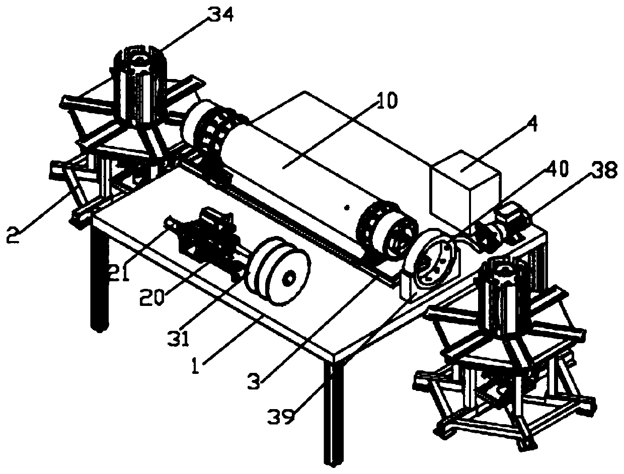
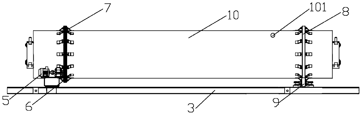
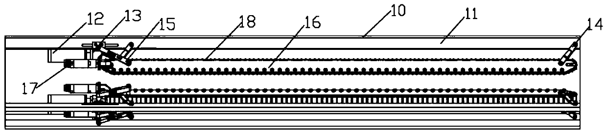
[0037] see Figure 1-7 As shown, the present invention is a kind of tight winding equipment for RTP composite pipe, including a stand 1 and two retractable racks 2, the two retractable racks 2 are symmetrically arranged on both sides of the stand 1, and the top of the stand 1 is installed There is a rectangular base 3, and a pipe delivery cylinder 10 is arranged on the top of the rectangular base 3, and the outer wall of the delivery cylinder 10 is respectively ins...


PUM


Abstract

The invention discloses tight winding equipment for RTP composite tubes. The tight winding equipment comprises a rack and two winding and unwinding frames; the two winding and unwinding frames are symmetrically arranged on the two sides of the rack; a rectangular base is mounted at the top of the rack; and a tube feeding barrel is arranged above the rectangular base. According to the tight windingequipment, connecting blocks are driven by piston rods of telescopic air cylinders to slide on kidney-shaped holes in raised lines, the connecting blocks cooperate with spring pins and rotating pinsto drive side connecting plates to move towards the RTP composite tubes, then three conveying tracks are driven to make contact with the outer walls of the RTP composite tubes, the conveying tracks are driven by second motors through driving wheels to rotate and begins to convey the RTP composite tubes, through inner structure arrangement of the tube feeding barrel, the equipment can be used for conveying the RTP composite tubes in different outer diameters, meanwhile, the three conveying tracks make contact with and convey the RTP composite tubes simultaneously, the condition of slipping of the RTP composite tubes during conveying is avoided effectively, and the conveying efficiency of the RTP composite tubes is higher through cooperation with winding and unwinding on the two sides.

Description

technical field [0001] The invention relates to the technical field of composite pipe production equipment, in particular to a tightly winding device for RTP composite pipes. Background technique [0002] Most RTP composite pipes adopt a three-layer structure, the inner layer is usually a corrosion-resistant and wear-resistant thermoplastic pipe, the middle layer is a reinforced layer for reinforcement, and the outer layer is an outer cladding layer for protection; among them, the reinforced layer is more It is made by winding and weaving reinforced fibers (such as "aramid fibers", and metal wires, etc.). [0003] The patent document (CN201810971307.4) discloses a winding device for RTP composite pipe winding filter belt. The winding device winds the reinforcing fiber on the outer surface of the plastic pipe through the winding seat and connects it tightly with glue. The outermost layer is set There is a filter belt layer, and the filter belt is wound on the outer surface o...

Claims


Application Information

Patent Timeline
Patent Type & Authority Applications(China)
IPC IPC(8): B29C53/56B29C53/80
CPCB29C53/56B29C53/80
Inventor 刘俊峰刘文江万刚曹操田祥军
Owner ANHUI JIELANTE NEW MATERIAL CO LTD
Why Eureka
Try Eureka