
Water taking pipeline system capable of realizing long-distance siphon across dam group mountain

A long-distance, water pipeline technology, applied in water conservancy projects, water conservancy engineering equipment, buildings, etc., can solve problems such as inability to use, and achieve the effect of speeding up efficiency and quickly fetching water

Active Publication Date: 2020-04-10
丰加梁
View PDF10 Cites 2 Cited by
  • Summary
  • Abstract
  • Description
  • Claims
  • Application Information

AI Technical Summary

Problems solved by technology

This water intake system is only suitable for some short distances, and a small amount of water transportation and transshipment. It cannot be used for some water transfer projects that need to climb over the mountain dams. Therefore, it is necessary to design a long-distance high-strength water intake system.

Method used


Image

  • Water taking pipeline system capable of realizing long-distance siphon across dam group mountain
  • Water taking pipeline system capable of realizing long-distance siphon across dam group mountain
  • Water taking pipeline system capable of realizing long-distance siphon across dam group mountain

Examples


Embodiment 1

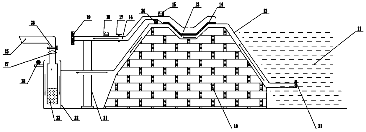
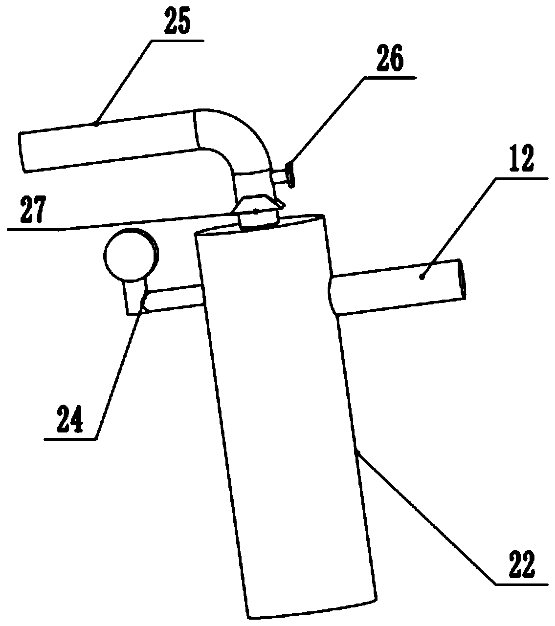
[0021] see Figure 1-3 , a long-distance siphon water intake pipeline system across dams and mountains, including a dams and mountains body 10, an active water level 11, a water delivery pipeline 12, and an outlet pipeline 25; the water delivery pipeline 12 is laid along the upper track of the dams and mountains body 10 On the top of the embankment mountains body 10, the right side of the embankment mountains body 10 is provided with an active water level 11, and the height of the active water level 11 is less than the right side height of the embankment mountains body 10, and the right end bottom of the water delivery pipeline 12 penetrates into the active water level The bottom of 11, the right-hand end of water pipeline 12 is equipped with one deck coarse filter screen 31 that is used to filter larger impurity particle in water. The left side part of the water delivery pipeline 12 is communicated with the water replacement pump pipeline 22, and the water delivery pipeline 1...

Embodiment 2

[0025] On the basis of Embodiment 1, a group of vacuum gauges 24 are connected to the upper part of the left side wall of the water replacement pump pipeline 22, and the vacuum value in the water replacement pump pipeline 22 is continuously detected by the vacuum gauge 24, and then the water inlet is obtained through the value. water level line. Said hydroelectric pump 23, second vacuum pump 18, solenoid valve 17, and first vacuum pump 15 are all electrically connected to a control system (not shown in the figure), and the control system can directly control the start and stop of each part of the whole system. When the vacuum gauge 24 detects that the water replacement pump pipeline 22 is in a non-vacuum state, the control system can directly shut down the water replacement electric pump 23, thereby realizing zero-energy water intake operation.


PUM


Abstract

The invention relates to the technical field of water transfer equipment, and discloses a water taking pipeline system capable of realizing long-distance siphon across a dam group mountain. The watertaking pipeline system comprises a dam group mountain body, a movable water level, a water conveying pipeline and a water outlet pipeline, wherein the water conveying pipeline is laid at the top of the dam group mountain body along the upper track of the dam group mountain body; the movable water level is arranged on the right side of the dam group mountain body; the bottom of the right end of thewater conveying pipeline permeates into the bottom of the movable water level; the left side part of the water conveying pipeline communicates with a water replacing pump pipeline; a section of siphon pipeline communicates with the water conveying pipeline positioned in the middle of the top of the dam group mountain body; the upper side of the siphon pipeline communicates with a group of air suction pipelines; the right sections of the air suction pipelines communicate with the top of the siphon pipeline through air filtering plates; the left end part of the water conveying pipeline communicates with the upper part of the right side of the water replacing pump pipeline; the water replacing pump pipeline is arranged to be a totally-closed vertical double-layer pipeline; and the top end ofthe water replacing pump pipeline communicates with the water outlet pipeline.

Description

technical field [0001] The invention relates to the technical field of water transfer equipment, in particular to a long-distance siphon water intake pipeline system across dams and mountains. Background technique [0002] In our country, with the development of urban construction, the consumption of water is huge. The uneven distribution of water across the country makes it extremely inconvenient to use water in various places. Therefore, it is necessary to transfer water from places with sufficient water sources to places where water resources are scarce. However, various water transfer and delivery systems today Compared with the device, the efficiency is average, resulting in slower water transfer speed and higher energy consumption. [0003] Chinese patent (notification number: CN 204059462 U, date of announcement: 2014.12.31) provides a water source water intake system, which is set on a slope near the water source, including a water intake structure for water intake ...

Claims


Application Information

Patent Timeline
IPC IPC(8): E02B1/00
CPCE02B1/00
Inventor 丰加梁丰加海
Owner 丰加梁
Learn More