

Prefabricated assembled type toughness combined shear wall structure and construction installation method thereof
A combined shear wall and prefabricated assembly technology, which is applied in the direction of walls, building components, building structures, etc., can solve the problems of easy deformation of steel plates and achieve the effect of convenient welding
- Summary
- Abstract
- Description
- Claims
- Application Information
AI Technical Summary
Problems solved by technology
Method used
Image

Examples
Embodiment 1
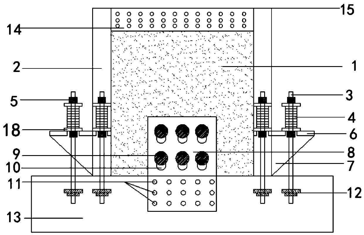
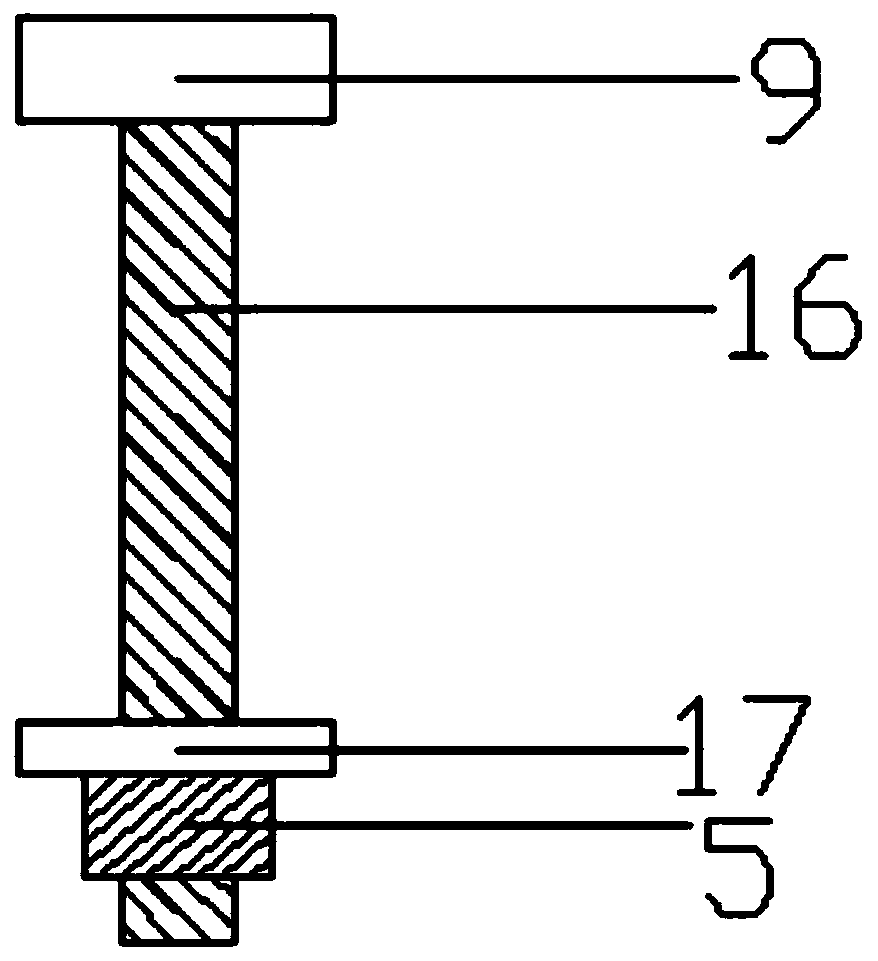
[0065] See attached figure 1 And attached figure 2 , the embodiment of the present invention discloses a prefabricated assembled ductile combined shear wall structure, which is constructed on a foundation 13; comprising: a steel plate combined shear wall 1, a steel tube concrete column 2, a shear steel plate 8, bolts 9, suspension pick plate 6, anchor rod 3 and limit steel plate 18;
[0066] The steel plate composite shear wall 1 is vertically arranged, and the bottom edge is attached to the top surface of the foundation 13, and the lower wall of the steel plate composite shear wall 1 is evenly opened with a plurality of circular holes;
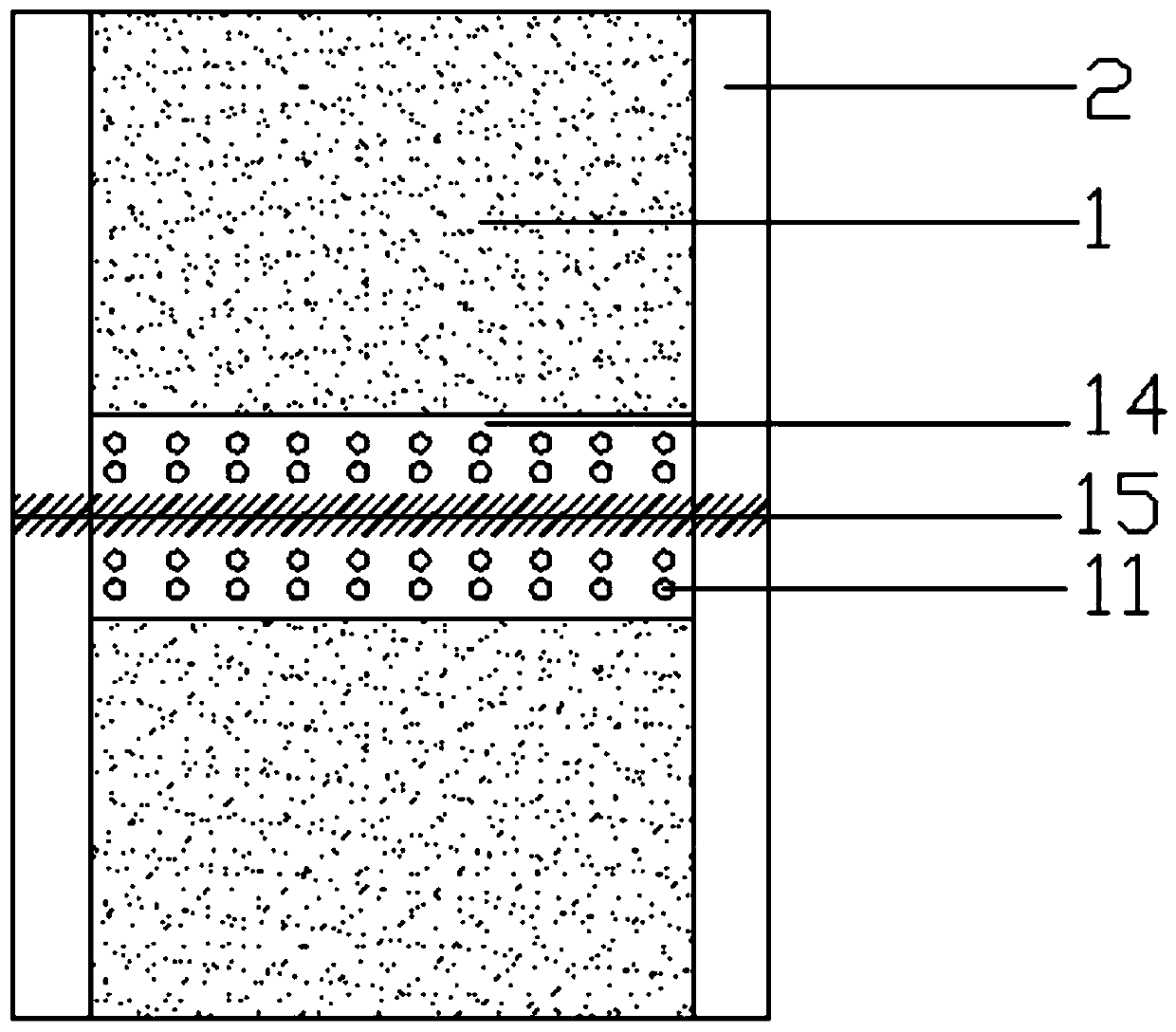
[0067] The steel tube concrete column 2 is fixed on the vertical sides of the steel plate composite shear wall 1;
[0068] The number of shear steel plates 8 is two, and they are attached and clamped to the lower part of the front and back of the steel plate composite shear wall 1; The vertical strip-shaped pre-opening hole 10 correspondi...
Embodiment 2
[0087] The embodiment of the present invention discloses a construction and installation method of a prefabricated assembly ductile composite shear wall structure, which specifically includes the following steps:
[0088] S1. Pre-assemble the disc spring group 4, the limit steel plate 18, the high-strength nut 5, the backing plate and the anchor rod 3;
[0089] S2. When pouring the foundation foundation 13, pre-embed the shear steel plate 8, the foundation embedded part 12 in the foundation foundation 13, and pre-embed and connect with the foundation embedded part 12 with a vertically upward pre-embedded anchor rod;
[0090] S3. Leave a circular hole in the steel plate composite shear wall 1 with the steel tube concrete column 2 during processing, embed a threaded sleeve in the circular hole, and weld the cantilever plate 6 and the support plate 7 on the column foot;
[0091] S4. Connect the steel plate composite shear wall 1 and the shear steel plate 8 through the bolt 9, and...
PUM
 Abstract
Description
Claims
Application Information