Catalytic combustion type MEMS gas sensor and working method thereof

A gas sensor, catalytic combustion technology, applied in the field of sensors, can solve problems such as poor safety and poor temperature isolation structure, and achieve the effects of low cost, fast response time and low power consumption

Pending Publication Date: 2020-04-10
武汉微纳传感技术有限公司
View PDF12 Cites 2 Cited by
  • Summary
  • Abstract
  • Description
  • Claims
  • Application Information

AI Technical Summary

Problems solved by technology

[0004] Aiming at the technical problems of poor temperature isolation structure and poor safety of combustible gas detection sensors in the prior art, the present invention provides a catalytic MEMS gas sensor and its working method

Method used


Image

  • Catalytic combustion type MEMS gas sensor and working method thereof
  • Catalytic combustion type MEMS gas sensor and working method thereof
  • Catalytic combustion type MEMS gas sensor and working method thereof

Examples


Embodiment 1

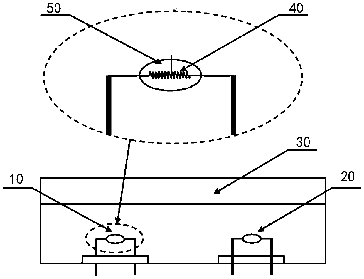
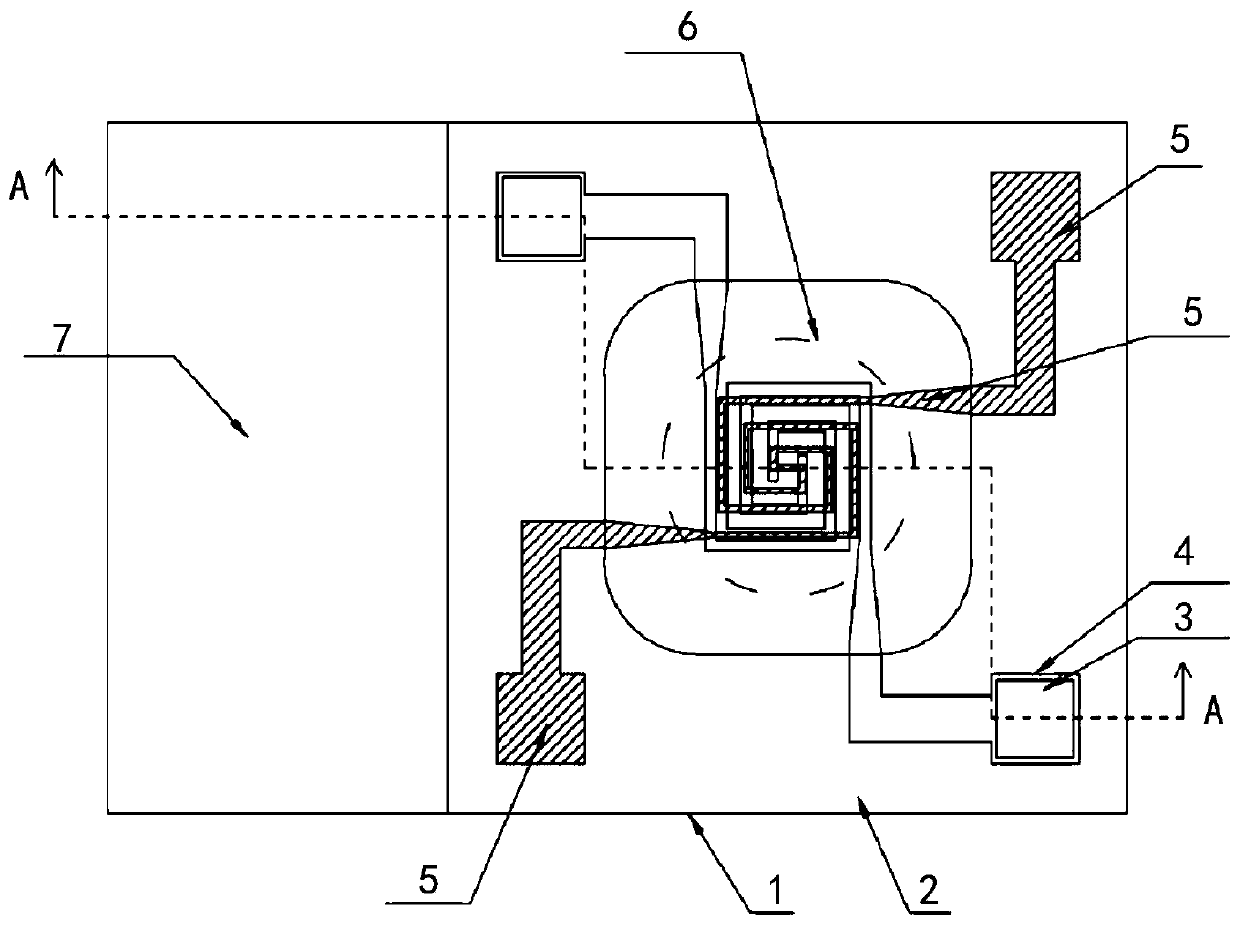
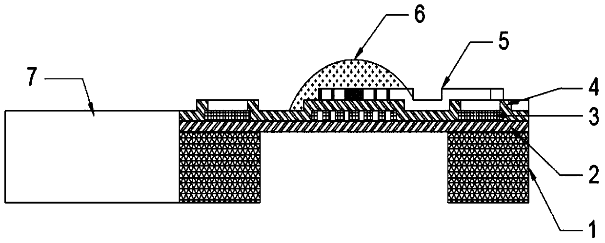
[0028] See figure 2 and image 3 The embodiment of the present invention provides a catalytic combustion type MEMS gas sensor, which includes a substrate 1, a first insulating support layer 2, a resistance heating layer 3, a second insulating support layer 4, a temperature sensing electrode layer 5, and a catalytic material layer 6 and microcontroller 7. The first insulating support layer 2 is arranged on the substrate 1, the resistance heating layer 3 is arranged on the first insulating support layer 2, and the second insulating support layer 4 covers the resistance heating layer 3; the temperature sensing electrode layer 5 is arranged on the On the second insulating support layer 4, the catalytic material layer 6 is attached to the temperature sensing electrode layer 5 and the upper part of the heating work area of ​​the second insulating support layer 4. The microcontroller 7 is arranged on the substrate 1, and the microcontroller 7 is electrically connected to the heating ...

Embodiment 2

[0038] See figure 2 and image 3 The embodiment of the present invention provides a working method of a catalytic combustion type MEMS gas sensor, wherein the working temperature of the MEMS gas sensor is 100-600°C. The method includes the following steps:

[0039] Step S10, the control microcontroller 7 measures the resistance values ​​of the heating resistance layer 3 and the temperature sensing electrode layer 5, and obtains the heating power and heating temperature of the heating resistance layer 3 and the temperature sensing electrode layer 5.

[0040] Among them, the resistance value of the resistance heating layer 3 is Rh, the power supply voltage is VCC, the heating power is controlled by PWM, and the PWM duty cycle Duty is D, then the heating power P is:

[0041] P=D*VCC / Rh 2 ;

[0042] The resistance of the temperature-sensing electrode layer is Rs, the temperature coefficient of the temperature-sensing electrode material is K, and the resistance of the temperature-sensing ...


PUM


Abstract

The invention relates to a catalytic MEMS gas sensor and a working method thereof. The catalytic MEMS gas sensor comprises a substrate, a first insulating support layer, a resistance heating layer, asecond insulating support layer, a temperature sensing electrode layer, a catalytic material layer and a microcontroller, wherein the first insulating support layer is arranged on the substrate, the resistance heating layer is arranged on the first insulating support layer, and the second insulating support layer covers the resistance heating layer; the temperature sensing electrode layer is arranged on the second insulating support layer, and the catalytic material layer is attached to the upper parts of the temperature sensing electrode layer and a heating working region of the second insulating support layer; and the microcontroller is arranged on the substrate. The working method comprises the steps that the microcontroller is controlled to obtain the heating power and the heating temperature of the heating resistance layer and the temperature sensing electrode layer; the working temperature of the resistance heating layer is controlled to be constant; and the gas sensor periodically works at a constant low temperature, a constant medium temperature and a constant high temperature. According to the catalytic combustion type MEMS gas sensor and the working method thereof provided by the invention, the sensor is short in response time, low in power consumption and low in cost.

Description

Technical field [0001] The invention relates to the technical field of sensors, in particular to a catalytic MEMS gas sensor and a working method thereof. Background technique [0002] As a chemical energy storage method, combustible gas is an important form of energy. Gas stoves and water heaters are widely used in the lives of residents; gasoline and diesel are still the main energy supply methods for automobiles, and hydrogen energy vehicles may be a better solution to environmental pollution in the future. Gas leakage can cause serious fire, explosion and poisoning accidents. Therefore, gas leak detection has spawned a huge market demand for combustible gas sensors. In addition, in coal mining, it is necessary to accurately monitor the combustible gas in mines and tunnels; in the petroleum and petrochemical industry, petrochemical products are usually flammable and explosive, and the concentration of combustible gas is also required. All of these require high-quality combu...

Claims


Application Information

Patent Timeline
Patent Type & Authority Applications(China)
IPC IPC(8): G01N27/12
CPCG01N27/12G01N27/128
Inventor 雷鸣刘曰利饶吉磊詹欢欢熊艳
Owner 武汉微纳传感技术有限公司
Why Eureka
Try Eureka