Low-offset high-precision static comparator

A comparator, high-precision technology, applied in the direction of pulse processing, electrical components, pulse technology, etc., can solve the problem of increasing the number of large series, and achieve the effect of increasing calibration accuracy, reducing offset voltage, and reducing power consumption

Active Publication Date: 2020-04-10
芯创智创新设计服务中心宁波有限公司
View PDF12 Cites 7 Cited by
  • Summary
  • Abstract
  • Description
  • Claims
  • Application Information

AI Technical Summary

Problems solved by technology

The offset voltage of the above technical solution does not adopt a special calibration method, which will prevent the increase of large series and naturally reduce the equivalent input offset of the latch

Method used


Image

  • Low-offset high-precision static comparator
  • Low-offset high-precision static comparator

Examples


Embodiment Construction

[0026] The present invention will be further described in detail below in conjunction with the accompanying drawings and specific embodiments.

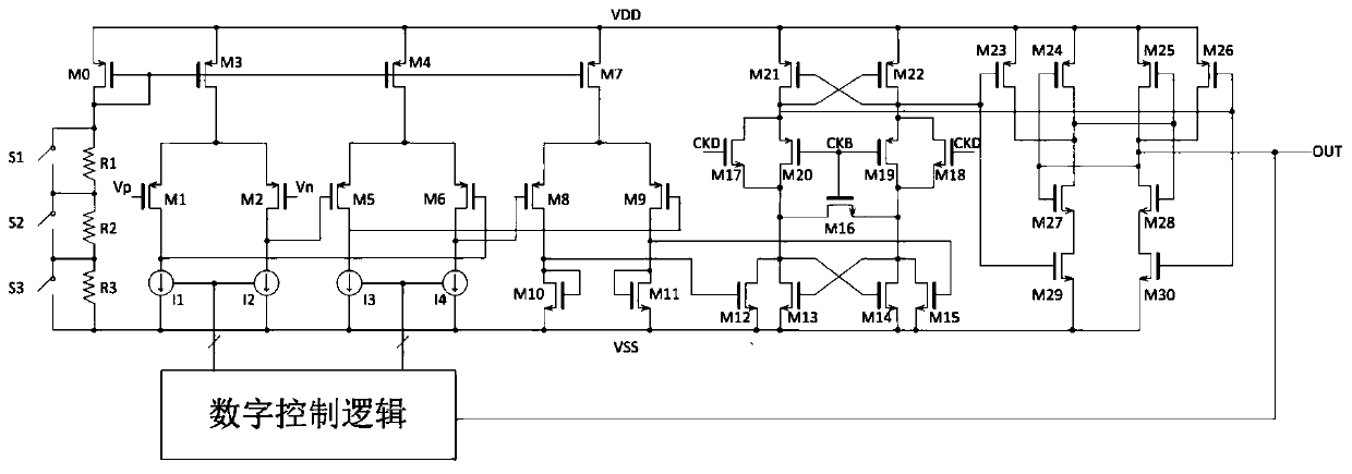
[0027] The present invention proposes a novel comparator architecture with offset calibration, which is composed of a self-bias circuit, a first-stage amplifier, a second-stage amplifier, a third-stage amplifier, a latch circuit, and a latch output stage, and has a relatively low offset voltage and high accuracy.

[0028] Such as figure 1 As shown, MOS transistor M0, resistors R1, R2, R3, and switches S1~S3 form a reference current source with controllable bias current, and S1~S3 are controllable switches used to adjust the resistance value, that is, the output value of the reference current. MOS tubes M1~M3, I1~I2 form the first stage amplifier, MOS tubes M4~M6, I3~I4 form the second stage amplifier, MOS tubes M7~M11 form the third stage amplifier, and I1~I4 are controllable current sources . MOS transistors M12-M22 form a latch c...


PUM


Abstract

The invention relates to a low-offset high-precision static comparator, and belongs to the technical field of integrated circuits. The comparator comprises: a bias circuit, which is used for controlling a bias current source and adjusting a resistance value, i.e., an output value of a reference current; the first-stage amplifier, the second-stage amplifier and the third-stage amplifier are used for amplifying input signals step by step; the latch circuit is used for latching an input signal and outputting the input signal to the latch output stage; the latch output stage is used for receivingthe signal of the latch circuit, amplifying the latch signal to full swing, and enhancing the driving capability of the output signal; and the digital control logic is used for receiving the signal ofthe latch output stage and controlling the controllable current source after level judgment so as to calibrate the offset of the comparator. By adopting the low-offset high-precision static comparator provided by the invention, the offset voltage of the comparator can be reduced, the precision of the comparator is improved, and the power consumption is reduced.

Description

technical field [0001] The invention belongs to the technical field of integrated circuits, in particular to a static comparator with low offset and high precision. Background technique [0002] Comparing two or more data items to determine whether they are equal, or to determine the size relationship and arrangement order between them is called comparison. A circuit or device capable of performing this comparison function is called a comparator. A comparator is a circuit that compares an analog voltage signal to a reference voltage. The two inputs of the comparator are analog signals, and the output is a binary signal 0 or 1. When the difference between the input voltages increases or decreases and the positive and negative signs remain unchanged, the output remains constant. [0003] Comparators are important circuits for converting analog signals into digital signals, and are widely used in circuits such as sensors, analog-to-digital converters, and high-speed interface...

Claims


Application Information

Patent Timeline
Patent Type & Authority Applications(China)
IPC IPC(8): H03K5/24
CPCH03K5/2463Y02D10/00
Inventor 赵喆朱敏
Owner 芯创智创新设计服务中心宁波有限公司
Why Eureka
Try Eureka