Straw deep-burying bionic spiral ditching device

A bionic spiral and spiral technology, applied in the direction of excavation/covering of trenches, planting methods, agricultural gas emission reduction, etc., can solve the problems of large trenching resistance, insufficient trenching depth, and difficulty in deep burial of straw, and reduce stickiness. Adhesion, simple and compact overall structure, good performance in soil

Inactive Publication Date: 2020-04-14
SHENYANG AGRI UNIV
View PDF2 Cites 0 Cited by
  • Summary
  • Abstract
  • Description
  • Claims
  • Application Information

AI Technical Summary

Problems solved by technology

Moreover, during the working process of the existing ditching device, the ditching depth is not enough, the ditching resistance is large, and it is difficult to realize deep burial of straw

Method used


Image

  • Straw deep-burying bionic spiral ditching device
  • Straw deep-burying bionic spiral ditching device
  • Straw deep-burying bionic spiral ditching device

Examples


Embodiment 1

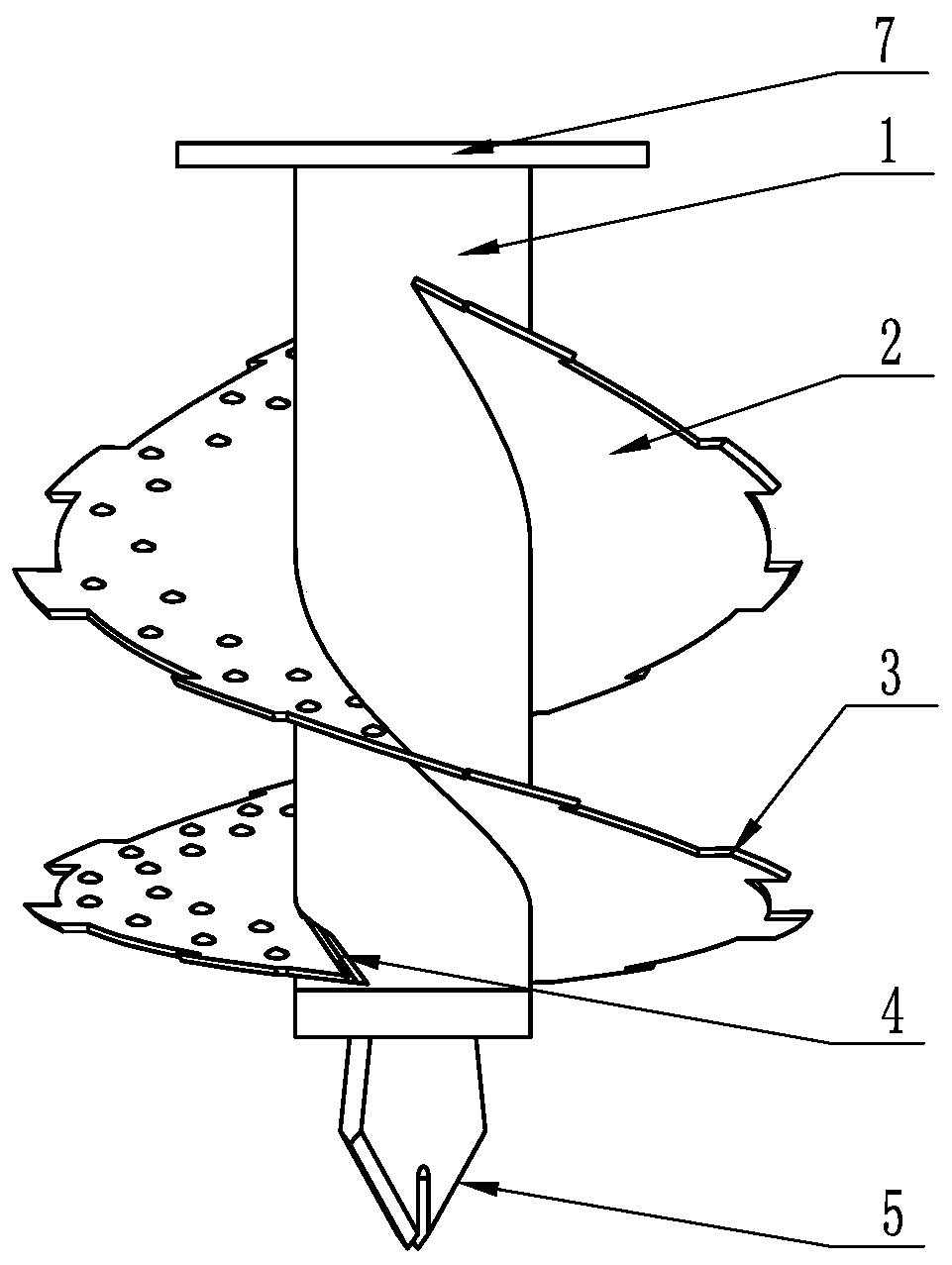
[0033] Embodiment 1: as figure 1 As shown, a bionic spiral ditching device for straw deep burial in the present invention includes a cutter shaft 1, a bionic spiral blade 2, a bottom soil cutting blade 4 and a knife tip 5, and the bionic spiral blade 2 is symmetrically arranged on the cutter shaft by a double helix 1, the force is balanced, the lead is increased, and the problems of soil blockage and poor linearity are solved; the bottom cutting blade 4 is set at the bottom of the bionic spiral blade 2, and the knife tip 5 is set at the ground end of the knife shaft 1 .

[0034] The flange connected to the cutter shaft 1 is connected with the reduction box to obtain power. The bionic helical blade 2 is welded to the cutter shaft 1 so as to rotate at a high speed to complete the upward conveying of the soil.

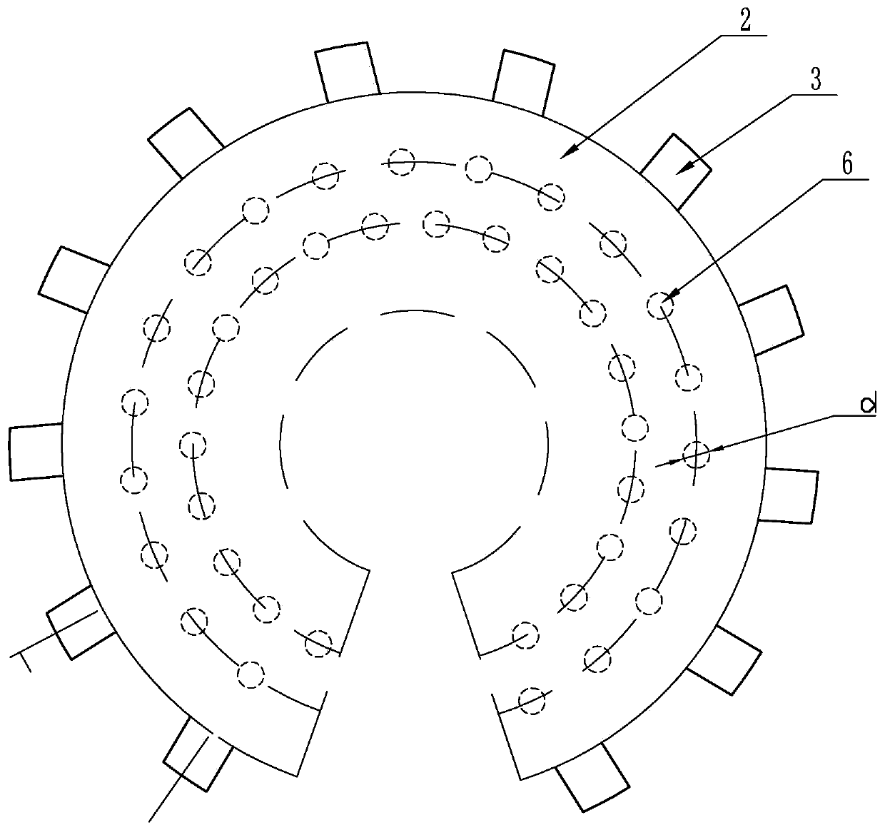
[0035] Such as figure 1 , figure 2 As shown, the surface of the bionic helical blade 2 in this example is provided with a plurality of spherical crowned protrusions ...

Embodiment 2

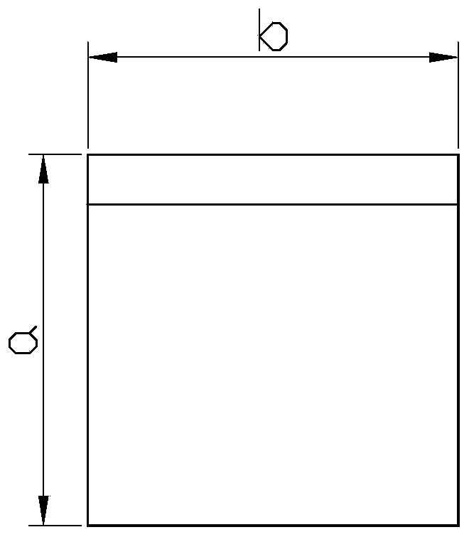
[0054] Embodiment 2: The difference between this example and Embodiment 1 is: in this example, the distance from the center of the outermost protrusion along the bionic spiral blade 2 to the edge of the blade is 20; this example sets 3 rows of protrusions, and the distance between two adjacent rows of protrusions 25mm; the external diameter d of the protrusion 6 of the spherical crown is 10mm, and the height is 5mm. The pitch P is 115mm; the blade angle λ of the blade tip is 25°, the maximum section outer diameter W of the blade is greater than the outer diameter D of the blade at the installation end, the maximum rotation diameter W of the blade is 100mm, and the height is 0.9W.

Embodiment 3

[0055] Embodiment 3: The difference between this example and Embodiment 1 is: in this example, the center of the outermost protrusion along the bionic spiral blade 2 is 40mm away from the edge of the blade; this example is provided with two rows of protrusions with a distance of 35mm; the spherical crown The external diameter d of the protrusion 6 is 16mm, and the height is 8mm. The pitch P is 250mm; the blade angle λ of the blade tip is 45°, the maximum section outer diameter W of the blade is greater than the outer diameter D of the blade at the installation end, the maximum rotation diameter W of the blade is 160mm, and the height is 1.2W.


PUM


Abstract

The invention discloses a straw deep-burying bionic spiral ditching device, and belongs to the technical field of agricultural machinery. The straw deep-burying bionic spiral ditching device comprisesa cutter shaft, bionic spiral blades, bottom soil cutting blades and a cutter point, wherein the bionic spiral blades are symmetrically arranged on the cutter shaft in a double-spiral manner; the bottom soil cutting blades are arranged at the bottom ends of the bionic double-spiral blades; and the cutter point is arranged at the grounding end of the cutter shaft. According to the straw deep-burying bionic spiral ditching device, the double-spiral blades are symmetrically arranged, so that the problem of non-uniform stress of a ditcher is solved, and meanwhile, the problem of poor linearity oftravelling of a machine tool is solved; the bottom soil cutting blades are arranged at the bottoms of the double-spiral blades, and the cutter point is arranged at the grounding end of the cutter shaft, so that the straw deep-burying bionic spiral ditching device is high in soil burying performance, low in resistance and simple and compact in overall structure; and large soil blocks are not formed in a ditching process, and an effect of deeply loosening soil can be achieved. The straw deep-burying bionic spiral ditching device is an initiative in agricultural machinery.

Description

technical field [0001] The invention belongs to the technical field of agricultural machinery, in particular to a bionic spiral ditching device for deep burial of straw. Background technique [0002] By deeply burying straw and returning it to the field, the environmental pollution caused by straw burning is reduced, and at the same time, the soil structure can be improved and soil fertility can be improved. There are many types of straw returning machines at home and abroad, but most of them can only return to the field directly on the surface or in a shallow layer. Corn straw is not easy to rot, and the surface returning to the field is prone to moisture in spring, which affects the emergence rate of crops. The long-term use of this model of straw returning in drylands in Northeast China has resulted in thickening and upward movement of the plow bottom layer and shallowing of the soil plow layer, which is not conducive to the growth of corn roots and restricts the increase...

Claims


Application Information

Patent Timeline
Patent Type & Authority Applications(China)
IPC IPC(8): A01C5/06
CPCA01C5/064Y02P60/20
Inventor 林静高文英李宏哲张吉营张军高希君苑景辉常亮马铁郝爽
Owner SHENYANG AGRI UNIV
Why Eureka
Try Eureka