Metal pipe chamfering equipment and working method thereof

A technology for metal pipe fittings and chamfering, applied in metal processing equipment, grinding/polishing equipment, manufacturing tools, etc., can solve problems such as reducing chamfering efficiency

Active Publication Date: 2020-04-14
宁波创青腾达机械有限公司
View PDF7 Cites 4 Cited by
  • Summary
  • Abstract
  • Description
  • Claims
  • Application Information

AI Technical Summary

Problems solved by technology

[0002] The metal round tube is a basic workpiece, which is widely used in modern society. After the metal round tube is cut and formed, there will be obvious burrs on the tube surface. In order to facilitate packaging and subsequent assembly, two parts of the metal tube are required. However, in the prior art, chamfering is mainly performed by cutting. On the one hand, cutting has high requirements for precision. When performing positioning cutting, the efficiency of chamfering will be greatly redu

Method used


Image

  • Metal pipe chamfering equipment and working method thereof
  • Metal pipe chamfering equipment and working method thereof
  • Metal pipe chamfering equipment and working method thereof

Examples


Embodiment Construction

[0037] The technical solutions in the embodiments of the present invention will be clearly and completely described below. Obviously, the described embodiments are only some of the embodiments of the present invention, but not all of them. Based on the embodiments of the present invention, all other embodiments obtained by persons of ordinary skill in the art without creative efforts fall within the protection scope of the present invention.

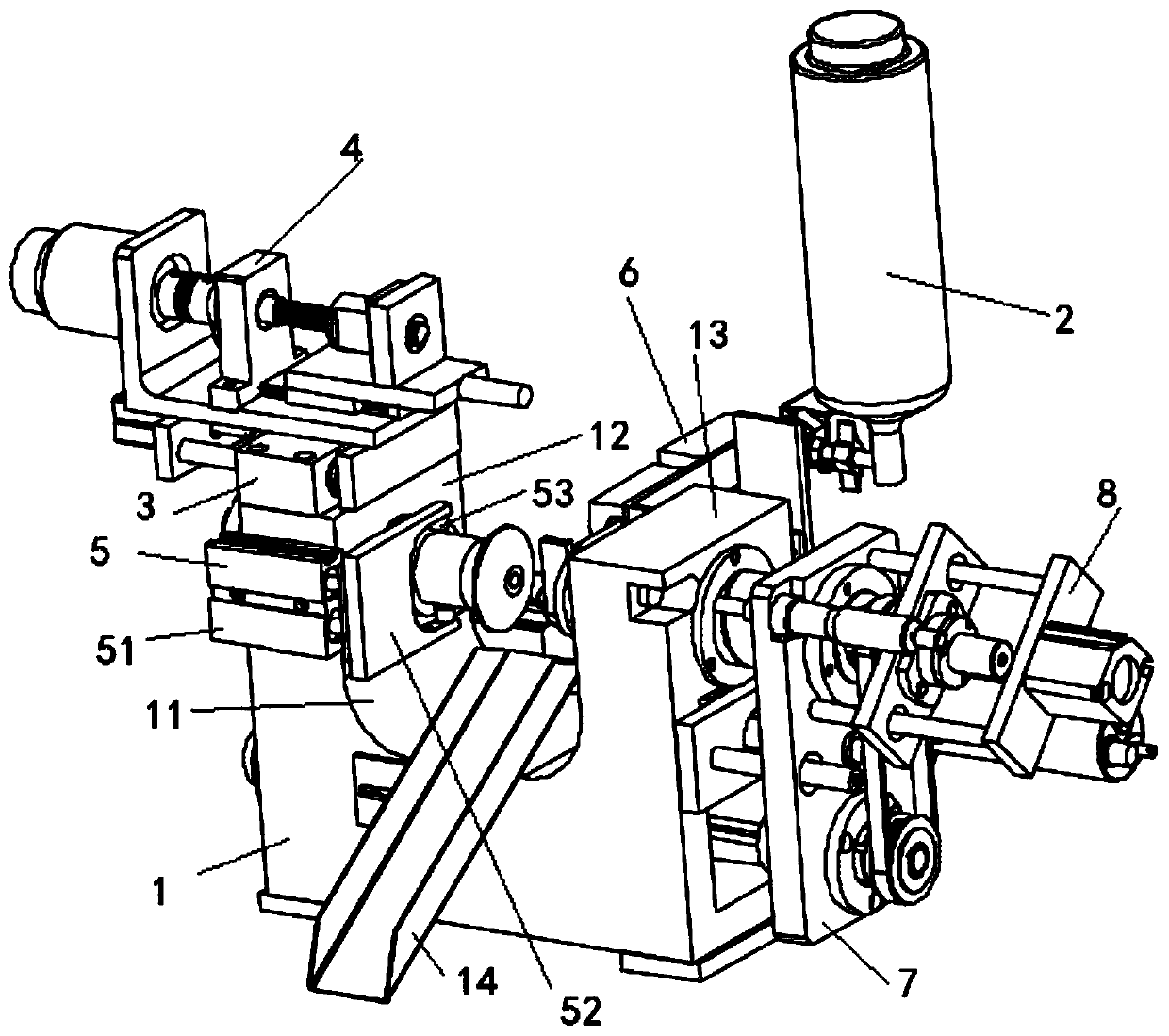
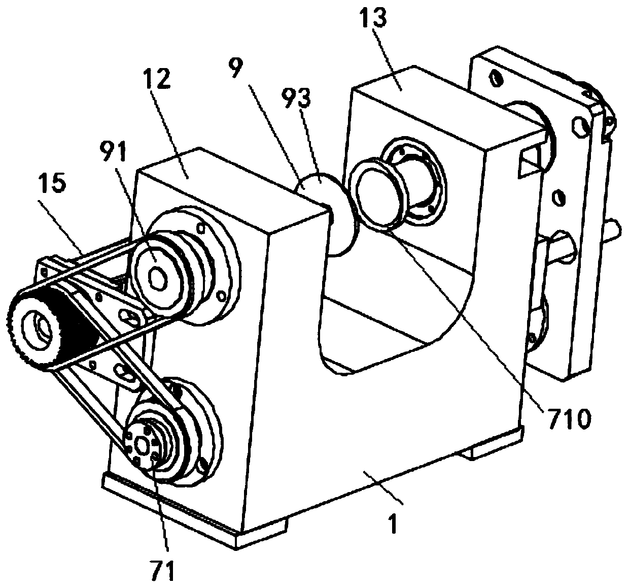
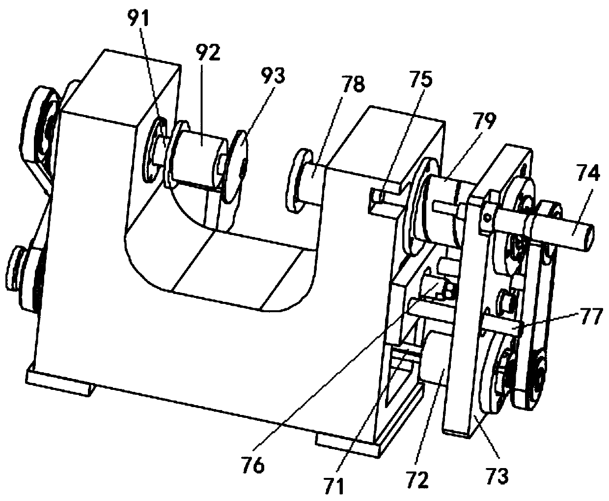
[0038] A metal pipe fitting chamfering equipment, such as Figure 1 to Figure 8 As shown, it comprises a main frame 1 with a U-shaped mouth 11, a left frame 12 and a right frame 13 respectively arranged at two ends of the main frame, a left chamfering rod 9 which is rotatably mounted on the left frame 12, and fixedly mounted on the left frame. The cutting device 3 and the lateral adjustment device 5 on the frame 12, the packaging film feeding device 4 fixedly installed on the cutting device 3, the right chamfering rod 7 mounted on the ri...


PUM


Abstract

The invention discloses metal pipe chamfering equipment and a working method thereof. According to the chamfering equipment, on one hand, burrs at the pipe opening can be rapidly removed, and a largenumber of metal scraps cannot be generated; in the chamfering process, the positions of an inner circle chamfering disc and an outer circle chamfering disc are actively adjusted, so that the chamfering work can be completed without spending a lot of time to position the metal pipe, and production efficiency is greatly improved; in addition, after the chamfering procedure of the metal pipe is completed, hot air is sprayed out through a hot air gun to dry the surface of the round pipe; after the surface of the round pipe is dried, the round pipe is wrapped by a thermal shrinkage film sent out bya packaging film feeding device; after wrapping is completed, the thermal shrinkage film is cut off through a cut-off device; and then, the thermal shrinkage film is heated through hot air sprayed out of the hot air gun to make thermal shrinkage film shrink and tightly wrap the surface of the round pipe, so that the chamfering and packaging integrated procedure of the metal pipe is completed, andthe round pipe machining efficiency is further improved.

Description

technical field [0001] The invention belongs to the technical field of processing equipment for metal parts, and in particular relates to a chamfering equipment for metal pipe fittings and a working method thereof. Background technique [0002] The metal round tube is a basic workpiece, which is widely used in modern society. After the metal round tube is cut and formed, there will be obvious burrs on the tube surface. In order to facilitate packaging and subsequent assembly, two parts of the metal tube are required. However, in the prior art, chamfering is mainly performed by cutting. On the one hand, cutting has high requirements for precision. When performing positioning cutting, the efficiency of chamfering will be greatly reduced, and Generally, only one of the inner circle or the outer circle is chamfered to avoid repeated positioning; in some processes, in order to reduce the time loss caused by positioning and improve the chamfering efficiency, only one end of the ro...

Claims


Application Information

Patent Timeline
IPC IPC(8): B24B9/04B24B41/00B24B47/20B24B57/02
CPCB24B9/04B24B41/005B24B47/20B24B57/02
Inventor 李雯雯李苗苗
Owner 宁波创青腾达机械有限公司
Why Eureka
Try Eureka