Karst tunnel drainage type drainage system

A drainage system and tunnel technology, applied in tunnels, drainage, tunnel lining and other directions, can solve the problems of difficult drainage of karst tunnels, and achieve the effects of improving drainage efficiency, expanding the scope of influence, and efficient drainage.

Pending Publication Date: 2020-04-14
CHINA RAILWAY ERYUAN ENG GRP CO LTD
View PDF0 Cites 6 Cited by
  • Summary
  • Abstract
  • Description
  • Claims
  • Application Information

AI Technical Summary

Problems solved by technology

[0003] The purpose of the present invention is to provide a karst tunnel drainage system for the problem of difficult drainage of karst tunnels in the prior art

Method used


Image

  • Karst tunnel drainage type drainage system
  • Karst tunnel drainage type drainage system
  • Karst tunnel drainage type drainage system

Examples


Embodiment 1

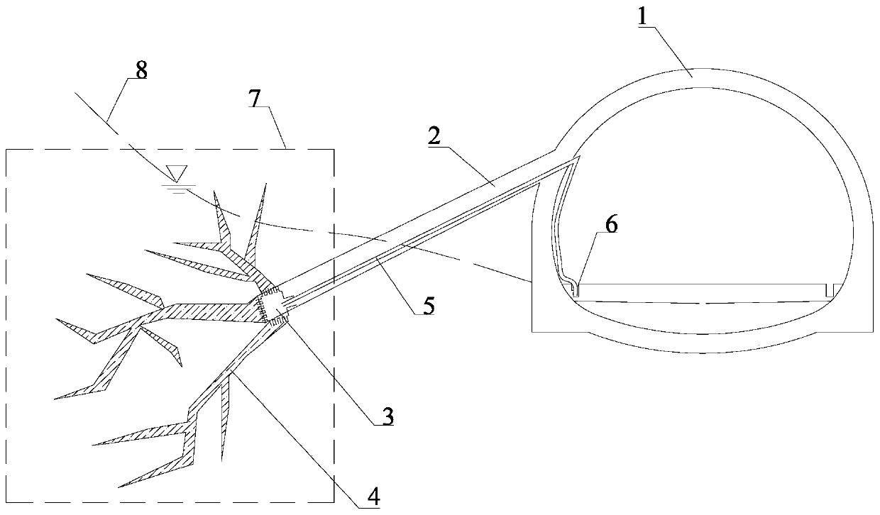
[0041] A karst tunnel drainage system includes a borehole 2, a drainage network, a drainage pipe 5 and a tunnel drainage ditch.

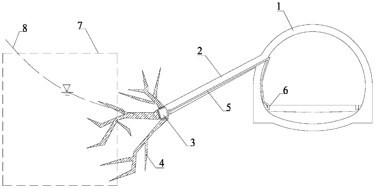
[0042] The borehole 2 is a downhill borehole, the inclination angle of the borehole 2 is 10°-30°, and the diameter of the borehole 2 is greater than or equal to 70mm. The borehole 2 is directly drilled into the karst development area 7 of the tunnel 1, such as figure 1 shown; or the borehole 2 is not drilled into the karst development area 7 of the tunnel 1, but is located near the karst development area 7, as figure 2 mentioned.

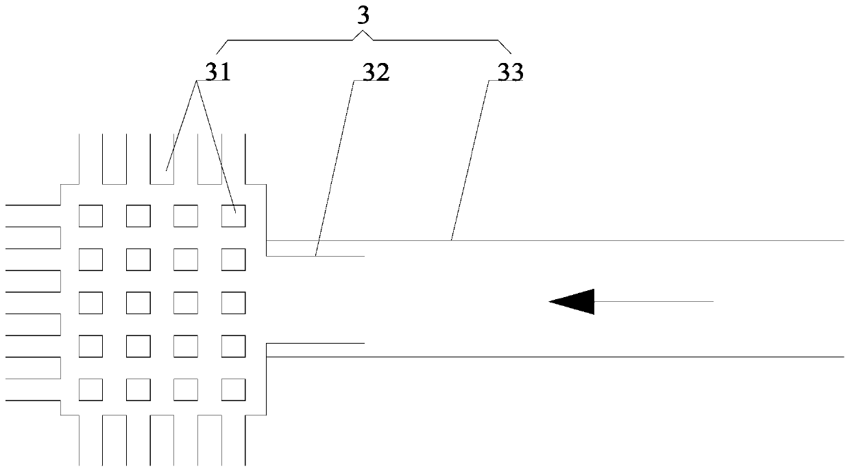
[0043] The bottom end of the borehole 2 is provided with a multi-nozzle casing 3, such as image 3As shown, the multi-nozzle sleeve 3 includes a grouting hole 31 , a plurality of injection holes 32 and a movable sleeve 33 , and all the injection holes 32 are arranged circumferentially along the multi-nozzle sleeve 3 . The grouting hole 31 is located in the borehole 2, the grouting hole 31 and the movable sleeve 33 are...

Embodiment 2

[0049] Such as Figure 1-Figure 5 Shown, a kind of karst tunnel drainage type drainage method comprises the following steps:

[0050] Step 1: Preliminarily determine the karst-developed area 7 of the tunnel 1 according to the geological survey results, and drill a down-dip borehole 2 from the arch wall of the tunnel 1 toward the karst-developed area 7 . If the borehole 2 can be drilled directly to the karst development area 7, then directly drill to the karst development area 7, if the borehole 2 cannot be directly drilled to the karst development area 7, then try to Drilling is carried out near the karst development area 7, so that after the permeable concrete 4 is injected, the drainage network formed can be at least partly located in the karst development area 7, thereby leading out the groundwater in the karst development area 7.

[0051] Step 2: Place a multi-nozzle casing 3 at the bottom of the borehole 2, the multi-nozzle casing 3 includes a grouting hole 31, a plurali...


PUM


Abstract

The invention discloses a karst tunnel drainage type drainage system. The system comprises drill holes, a drainage network, drainage pipes and a tunnel drainage ditch, wherein the drill holes are downtilt drill holes, the drill holes are the downtilt drill holes formed through drilling from a tunnel arch wall into a karst development area, the drainage network is located at a soil body or rock mass near the bottom ends of the drill holes, at least part of the drainage network is located in the karst development area, the drainage network comprises a plurality of cracks, water permeable concrete fills the cracks, all the cracks communicate with one another, the drainage pipes are laid in the drill holes, water inlets of the drainage pipes communicate with the drainage network, water outletsof the drainage pipes communicate with the tunnel drainage ditch, the elevations of the water inlets of the drainage pipes are lower than the elevations of the water outlets of the drainage pipes, and the elevations of the top ends of the drill holes are higher than the elevations of the water outlets of the drainage pipes. According to the karst tunnel drainage type drainage system, the siphoniceffect is utilized, so long as underground water is converged, redundant underground water in the tunnel surrounding rock can be automatically and efficiently discharged out in real time, no externalpower is needed, and manual maintenance is not needed.

Description

technical field [0001] The invention relates to the technical field of tunnel engineering, in particular to a karst tunnel drainage system. Background technique [0002] In recent years, my country's railways, highways and other transportation undertakings have developed rapidly, and the number and mileage of tunnels have continued to increase. Affected by the complex geological environment and hydrogeological conditions, the construction and operation of the tunnel still faces many engineering problems. Karst tunnels are widely distributed in southwest China, and karst water has caused great harm to the tunnel lining structure. The water pressure acts on the lining, changing the stress characteristics of the lining structure, and the large water pressure behind the lining increases the load on the back of the tunnel structure, causing The occurrence of diseases such as cracking of tunnel lining, uplift of inverted arch, mud turning and so on. Therefore, it is particularly...

Claims


Application Information

Patent Timeline
Patent Type & Authority Applications(China)
IPC IPC(8): E21F16/02E21F17/00E21D11/10F04F10/00
CPCE21D11/10E21F16/02E21F17/00F04F10/00
Inventor 范雲鹤罗禄森赵万强郑长青周路军喻渝张永平何昌国匡亮蒋立何洋刘佩斯唐思聪袁伟杨学中刘祥华阳
Owner CHINA RAILWAY ERYUAN ENG GRP CO LTD
Why Eureka
Try Eureka