Reinforced flow guide type large-flow injection device of gaseous fuel engine

A gas fuel and injection device technology, which is applied in combustion engines, internal combustion piston engines, engine components, etc., can solve the problems affecting the quality of natural gas combustion, the inability of injection holes to play a good role in guiding gas flow, and hindering the efficiency of natural gas intake. problems, to achieve the effect of improving mixing, improving combustion quality, and reducing NOx emissions

Inactive Publication Date: 2020-04-14
HARBIN ENG UNIV
View PDF8 Cites 1 Cited by
  • Summary
  • Abstract
  • Description
  • Claims
  • Application Information

AI Technical Summary

Problems solved by technology

The purpose of this structure is to change the injection hole of the injection duct from one injection hole to multiple side hole injection, which can more effectively improve the uniformity of gas mixing, thereby improving the engine performance, but this device is only suitable for natural gas with small flow and small aperture Engine, when the engine needs to inject a large amount of natural gas, the intake efficiency of natural gas will be hindered because the hole diameter is too small. If the size of the injection hole is changed to improve this situation, the ratio of the depth of the injection hole to the diameter of the injection hole will be too small. Better gas diversion effect, thus affecting the quality of natural gas and air mixing, and then affecting the quality of natural gas combustion in the cylinder

Method used


Image

  • Reinforced flow guide type large-flow injection device of gaseous fuel engine
  • Reinforced flow guide type large-flow injection device of gaseous fuel engine
  • Reinforced flow guide type large-flow injection device of gaseous fuel engine

Examples


Embodiment Construction

[0018] The present invention is described in more detail below in conjunction with accompanying drawing example:

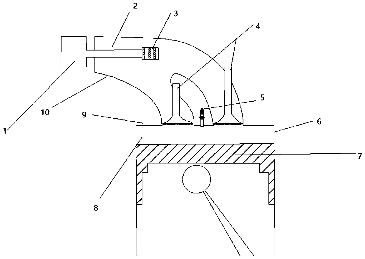
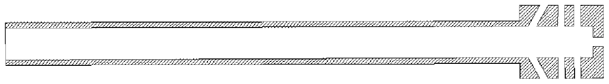
[0019] combine Figure 1-5 , the present invention includes intake manifold 10, cylinder head 9, gas injection valve 1, gas guide pipe 2, gas nozzle 3, gas nozzle 3 is connected with gas injection valve 1 through gas guide pipe 2, gas nozzle 3 Go deep into the intake manifold, thicken the pipe wall near the end of the gas nozzle, and process multiple groups of nozzle holes at the thickened part. The center of each group of nozzle holes is evenly distributed along the circumference of the pipe wall, and each group of nozzle holes The center is composed of a plurality of nozzle holes, thickening treatment is carried out at the nozzle to reduce the diameter-depth ratio of the nozzle holes, so that each nozzle hole has a better flow guiding effect, and the gas nozzle 3 has a porous structure. The axial direction of the injection hole and the jet flow can pass through...


PUM


Abstract

The invention aims to provide a reinforced flow guide type large-flow injection device of a gaseous fuel engine. The device comprises an air cylinder cover, an air cylinder wall, a piston, an air inlet channel, a fuel gas injection valve and a fuel gas nozzle, wherein the air cylinder cover is located above the air cylinder wall, the piston is located in the air cylinder wall, the air inlet channel is formed on the air cylinder cover, the fuel gas nozzle is located in the air inlet channel and in front of the air inlet valve, the fuel gas injection valve is located outside the air inlet channel, the fuel gas nozzle is connected with the fuel gas injection valve through a fuel gas flow guide pipe, spraying holes are formed at a tail end of the fuel gas nozzle in the circumferential direction, the spraying holes distributed in the same circumference of the tail end of the fuel gas nozzle are a set of spraying holes, each set of spraying holes are evenly distributed in the circumferentialdirection, and the diameter-depth ratio of the spray holes is reduced by thickening a tail end part of the fuel gas nozzle. The device is advantaged in that the fuel gas flow guide effect of a multi-hole spraying nozzle can be enhanced, and the requirements for different working conditions and different emission properties of an engine can be met through different spraying hole arrangement schemes.

Description

technical field [0001] The invention relates to a fuel injection device, in particular to a gas fuel engine injection device. Background technique [0002] With the increasingly severe energy crisis and environmental pollution, domestic and foreign engine manufacturers are actively researching and exploring various energy-saving and emission-reducing technologies. Natural gas has become the most promising alternative energy source due to its advantages such as wide sources, high calorific value and less pollution. Among them, the lean combustion technology can reduce the intake throttling loss, can adopt a higher compression ratio, and the combustion temperature is lower, so that the engine produces higher thermal efficiency and lower NOx emissions, and has become an important technology for energy saving and emission reduction of the engine. measure. For natural gas engines with perforated sidewall gas nozzles with porous structures, if the nozzle is not thickened for lar...

Claims


Application Information

Patent Timeline
Patent Type & Authority Applications(China)
IPC IPC(8): F02M21/02
CPCF02M21/0278Y02T10/30
Inventor 杨立平满明龙宋恩哲姚崇董全
Owner HARBIN ENG UNIV
Why Eureka
Try Eureka