Interference phase shift sensitivity enhancing method based on moire fringes

A Moiré fringe and interference phase shift technology, applied in measurement devices, instruments, optical devices, etc., can solve the problems of insufficient interference phase shift sensitivity, small optical path difference offset, etc. good compatibility

Active Publication Date: 2020-04-14
INST OF OPTICS & ELECTRONICS - CHINESE ACAD OF SCI
View PDF10 Cites 0 Cited by
  • Summary
  • Abstract
  • Description
  • Claims
  • Application Information

AI Technical Summary

Problems solved by technology

[0008] The technical problem to be solved by the present invention is: for the fixed delay interferometer and the asymmetric space heterodyne interferometer, the optical path difference offset is small, and the interferometric phase shift sensitivity is not enough, a moiré-based interferometric phase shift is proposed Sensitivity Enhancement Method

Method used


Image

  • Interference phase shift sensitivity enhancing method based on moire fringes
  • Interference phase shift sensitivity enhancing method based on moire fringes
  • Interference phase shift sensitivity enhancing method based on moire fringes

Examples


Embodiment 1

[0030] Embodiment 1 of the present invention is a method for enhancing the sensitivity of an interference phase shift of a fixed-delay interference instrument by using Moiré fringes.

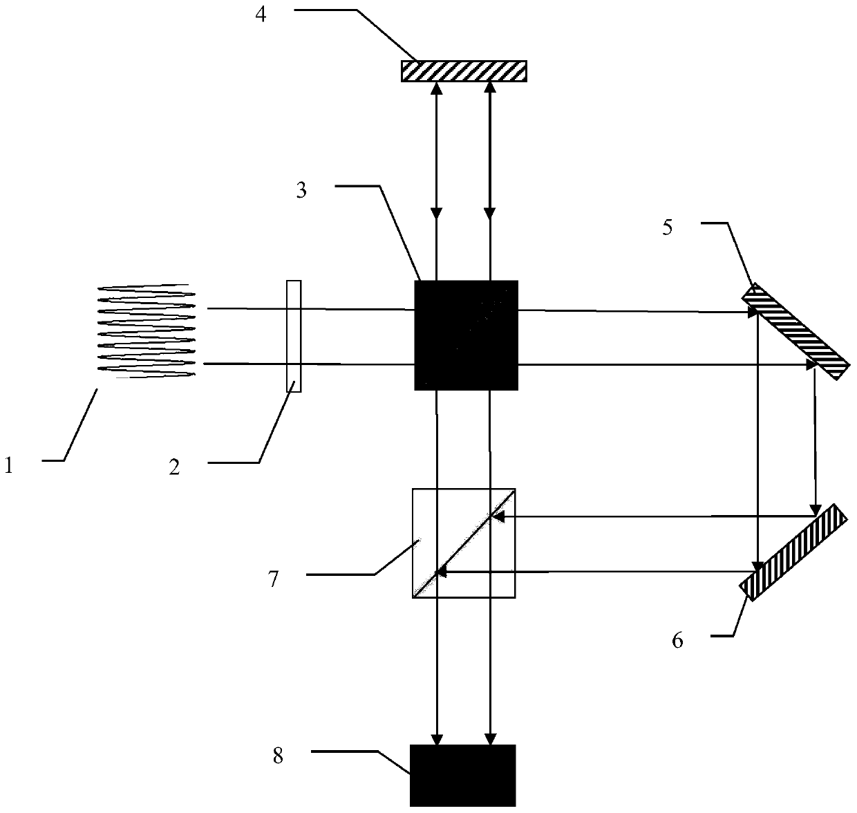
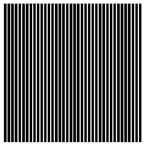
[0031] Such as figure 1 As shown, the interference fringe light field 1 output by the fixed-delay interferometer is generated by a laser with a wavelength of 633nm. The aperture of the interference fringe light field is 25mm. Period is 260μm, such as figure 2 As shown, according to the formula It can be obtained that the divergence angle of the interference fringe light field is about 1.2 mrad, which is similar to a beam of parallel light beams carrying interference fringe distribution. The parallel light beam first passes through the polarizer 2, so that the polarization direction of the interference fringe light field 1 is 45° to the vertical direction, ensuring that the light intensity of the p-polarization component and the s-polarization component are equal, and then vertically incident...

Embodiment 2

[0033] Embodiment 2 of the present invention is a method for enhancing the sensitivity of the interferometric phase shift of an asymmetric spatial heterodyne interferometer by using Moiré fringes.

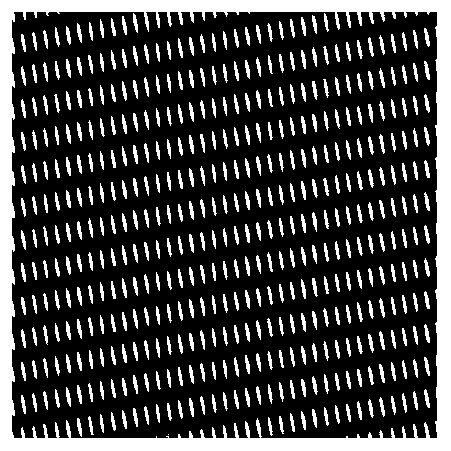
[0034] Such as Figure 4 As shown, the interference fringe light field 1 output by the asymmetric spatial heterodyne interferometer is produced by the green line of oxygen atoms with a wavelength of 557.7nm. The period is 200μm, such as Figure 5 As shown, according to the formula It can be obtained that the divergence angle of the interference fringe light field is about 1.4 mrad, which is similar to a beam of parallel light beams carrying interference fringe distribution. Since the light source is natural light, has no polarization characteristics, and the coherence length is very short, interference between the two sets of interference fringes formed on the detector is impossible, so there is no need to add a polarizer in the optical path. This parallel light beam is vertical...


PUM


Abstract

The invention discloses an interference phase shift sensitivity enhancing method based on moire fringes. The method comprises the steps that an interference fringe light field formed by a spatial modulation type interferometer passes through a polaroid and then enters a common beam splitter prism, reflected light is reflected by a first plane mirror and then returns along an original light path, passes through the common beam splitter prism again and then enters an array detector through a polarization beam splitter prism, and a set of interference fringe distribution is formed; and transmission light is reflected twice in sequence, then enters the polarization beam splitting prism, and enters the array detector after being reflected, so that another group of interference fringe distribution with opposite fringe orientations is formed. A third plane mirror is adjusted, so that an included angle is formed between two groups of interference fringes on the array detector, and moire fringes are formed. When phase shift occurs to the interference fringes, obvious displacement occurs to the moire fringes. The interference phase shift sensitivity enhancing method based on the moire fringes has universality and can effectively improve the measurement sensitivity of a spatial modulation type interference instrument.

Description

technical field [0001] The invention belongs to the field of interference instrument design, in particular to a method for enhancing the sensitivity of interference phase shift based on Moiré fringes. Background technique [0002] Interferometry technology is an important branch in the field of optical technology. It is a measurement technology based on light wave interference. It records the information of the target to be measured in the form of interference fringes. By analyzing and processing the phase of the interference fringes, the obtained The physical quantity to be measured is widely used in the field of optical detection. [0003] In the application field of Doppler velocimetry using interferometry technology, it is often necessary to accurately measure the phase shift of interference fringes. At present, the interferometers used to measure Doppler velocity mainly include Fabry-Perot interferometer, Michelson interferometer, fixed delay interferometer and asymmet...

Claims


Application Information

Patent Timeline
Patent Type & Authority Applications(China)
IPC IPC(8): G01B9/02
CPCG01B9/0201
Inventor 方亮况银丽程欣彭翔张辉刘恩海
Owner INST OF OPTICS & ELECTRONICS - CHINESE ACAD OF SCI
Why Eureka
Try Eureka