Surface-mounted permanent magnet rotor disc of high-strength axial magnetic field motor

An axial magnetic field, permanent magnet rotor technology, applied in the direction of magnetic circuit rotating parts, magnetic circuit shape/style/structure, electromechanical devices, etc. To solve the problems of air gap and other problems, to solve the problem of structural safety, easy and convenient transfer, and reduce the temperature rise of the rotor

Active Publication Date: 2020-04-14
NANJING UNIV OF SCI & TECH
View PDF16 Cites 22 Cited by
  • Summary
  • Abstract
  • Description
  • Claims
  • Application Information

AI Technical Summary

Problems solved by technology

[0003] Patent CN 101860098 A discloses a disc-type permanent magnet motor rotor, using pressing blocks and screws to fix the permanent magnets to the metal magnetic shielding plate of the motor, so that the permanent magnets are tightly connected to the metal magnetic shielding plate of the motor, but this method destroys the The integrity of the permanent magnet structure will cause stress concentration at the fastening connection during high-speed rotation, which greatly reduces the strength of the rotor permanent magnet
Patent CN 108233656 A discloses an ultra-high-speed disc-type permanent magnet synchronous motor. The rotor of the U-shaped protective sleeve is used to fix the permanent magnet, which increases the axial air gap, and the selection of its material is particularly critical. Conductive properties, while mechanical strength is better, which brings many technical difficulties to engineering design

Method used


Image

  • Surface-mounted permanent magnet rotor disc of high-strength axial magnetic field motor
  • Surface-mounted permanent magnet rotor disc of high-strength axial magnetic field motor
  • Surface-mounted permanent magnet rotor disc of high-strength axial magnetic field motor

Examples


Embodiment Construction

[0031] For axial field permanent magnet motors, the structural strength of the rotor directly affects the maximum speed and power density of this type. With the continuous development of axial field motor technology, the protection of permanent magnets and the improvement of rotor strength have become the field of this field. An important research hotspot and direction.

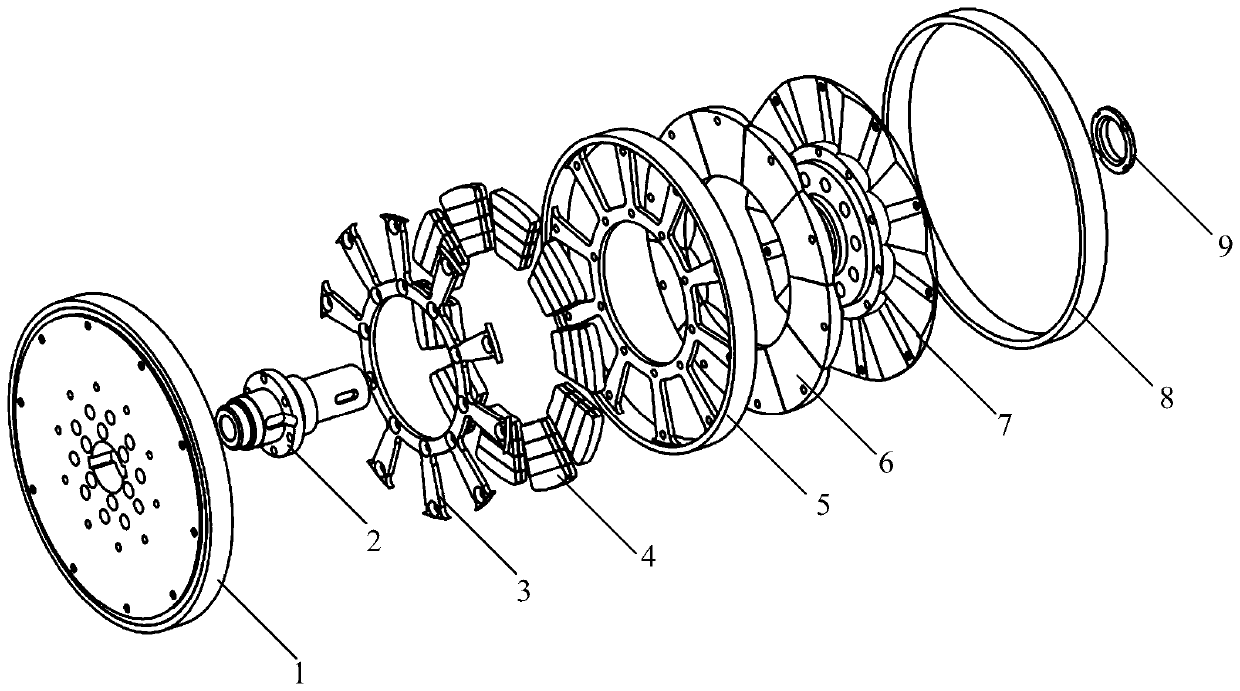
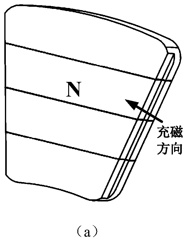
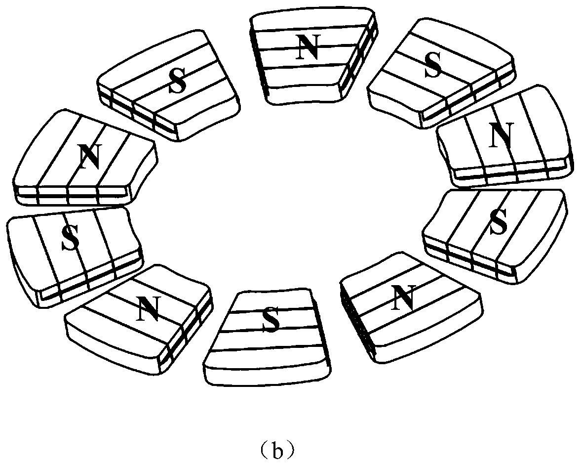
[0032] The present invention proposes a surface-mounted permanent magnet rotor disk for a high-strength axial magnetic field motor, which includes two rotor disks 1 mounted symmetrically on the rotating shaft 2 facing each other, and a space is left between the two rotor disks 1 for installing the stator disk; Each rotor disc 1 includes spoke-shaped permanent magnet pressure plate 3 of polymer material, trapezoidal permanent magnet 4, fixed frame 5 of polymer material, rotor magnetic back yoke 6, rotor support plate 7 and carbon fiber sheath 8 arranged in sequence;

[0033] The rotor magnetically conductive b...


PUM


Abstract

The invention discloses a surface-mounted permanent magnet rotor disc of a high-strength axial magnetic field motor, which comprises two rotor discs symmetrically mounted on a rotating shaft face to face, and a gap is reserved between the two rotor discs for mounting a stator disc; each rotor disc comprises a high polymer material spoke-shaped permanent magnet pressing plate, a trapezoidal permanent magnet, a high polymer material fixing frame, a rotor magnetic conductive back yoke, a rotor supporting plate and a carbon fiber sheath which are arranged in sequence. The rotor magnetic conductiveback yoke is mounted on the back surface of the high polymer material fixing frame; a trapezoidal groove is formed between inner and outer rings of the high polymer material fixing frame; trapezoid permanent magnets are alternately arranged in the circumferential direction of the rotor magnetic conductive back yoke, and stepped notches are formed in the two sides of the front face of each trapezoid permanent magnet and connected with the polymer material fixing frame through polymer material spoke-shaped permanent magnet pressing plate. A carbon fiber protection ring sleeve is arranged outside the high polymer material fixing frame; and a rotor support plate is mounted on the outer side of the rotor magnetic conductive back yoke. The surface-mounted permanent magnet rotor disc has the advantages of small rotor loss, high structural strength and good installation manufacturability.

Description

technical field [0001] The invention relates to the technical field of axial flux permanent magnet motors, in particular to a surface-mounted permanent magnet rotor disc of a high-strength axial magnetic flux motor. Background technique [0002] Compared with traditional radial field permanent magnet motors, axial field permanent magnet motors have significant advantages such as compact structure, high torque density, and high efficiency. The single-rotor double-stator structure is more common. The torque of the axial magnetic field permanent magnet motor is proportional to three times the outer diameter, so its torque density has a significant advantage under the structural constraints of a small long diameter. Very good application prospects. Different from the radial motor, the outer diameter of the rotor of the axial field motor is generally the same as that of the stator, so the outer diameter of the rotor is larger, resulting in a large moment of inertia, and the per...

Claims


Application Information

Patent Timeline
Patent Type & Authority Applications(China)
IPC IPC(8): H02K16/02H02K1/27H02K1/28
CPCH02K1/27H02K1/28H02K16/02
Inventor 耿伟伟王晶李强张卓然朱婷
Owner NANJING UNIV OF SCI & TECH
Why Eureka
Try Eureka