Vamp polishing device for shoemaking production line

A production line and shoe upper technology, applied in grinding/polishing safety devices, shoemaking machinery, applications, etc., can solve the problems of limited work efficiency, insufficient connection, high labor intensity, etc., to ensure accuracy and not easily deformed by force , The effect of reducing maintenance costs

Active Publication Date: 2020-04-17
FUDAN UNIV
View PDF15 Cites 3 Cited by
  • Summary
  • Abstract
  • Description
  • Claims
  • Application Information

AI Technical Summary

Problems solved by technology

[0003] The quality of the shoe shape mostly depends on the shoe last. The shoe last is based on the human foot. A piece of wood is hand-carved to make a plastic or metal model. Two things must be considered, after the shoe last is made, in the normal shoe making process, put the upper on the shoe last, use needle-nose pliers (we call it "net pliers") to knock the nails, and fix the upper On the shoe last, brush the glue to paste the upper surface, pull out the small nails after the upper surface is glued, and then paste the sole on the upper surface, and finally use the top press machine to reinforce and press the top. Although the economy develops, the operation level is getting better and better. The more intelligent it is, but many of the production of shoes are also set up with manual operation stations, and then connected into an assembly line for operation. The assembly line form of division of labor and cooperation improves work efficiency. To a certain extent, skilled operation also guarantees quality. , but the labor intensity of the workers is very high, and the connection between the various tasks on the assembly line is still not smooth enough. Most of them are transmitted by conveyor belts. The specific execution of the work is still manual, and the intensity is high, which also limits the further improvement of work efficiency to a certain extent.

Method used


Image

  • Vamp polishing device for shoemaking production line
  • Vamp polishing device for shoemaking production line
  • Vamp polishing device for shoemaking production line

Examples


Embodiment Construction

[0038] It should be noted that, in the case of no conflict, the embodiments of the present invention and the features in the embodiments can be combined with each other.

[0039] In describing the present invention, it should be understood that the terms "center", "longitudinal", "transverse", "upper", "lower", "front", "rear", "left", "right", " The orientations or positional relationships indicated by "vertical", "horizontal", "top", "bottom", "inner" and "outer" are based on the orientations or positional relationships shown in the drawings, and are only for the convenience of describing the present invention and Simplified descriptions, rather than indicating or implying that the device or element referred to must have a particular orientation, be constructed and operate in a particular orientation, and thus should not be construed as limiting the invention. In addition, the terms "first", "second", etc. are used for descriptive purposes only, and should not be interpreted...


PUM


Abstract

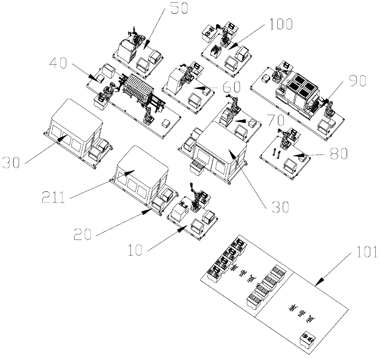
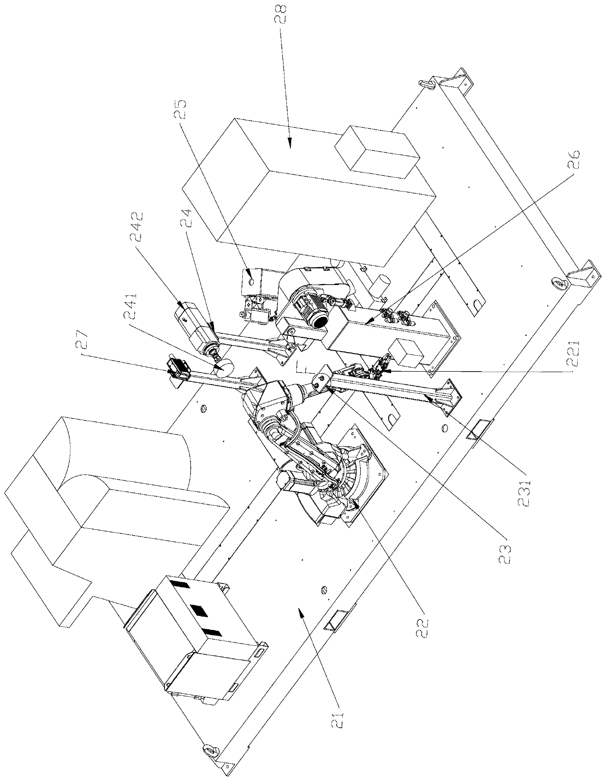
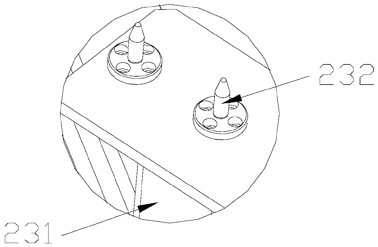
The invention provides a vamp polishing device for a shoemaking production line, and belongs to the field of shoemaking equipment. The device includes a tray bottom plate, and includes a six-axis manipulator, a hand reversing table support, a shoe side face polishing assembly, a shoe sole polishing assembly, a shoe heel polishing assembly and a laser scanning assembly, which are arranged on the tray bottom plate. The hand reversing table support is used for being matched with the six-axis manipulator to adjust the direction and the position of the shoe tree; the shoe side face polishing assembly comprises a first polishing wheel used for polishing the side face of a shoe; the shoe sole polishing assembly comprises a second polishing wheel used for polishing the bottom of the shoe; the shoeheel polishing assembly comprises a tensioning wheel, a dull polish belt is arranged on the outer side of the tensioning wheel, and the dull polish belt swings up and down under the action of a grinding shell to grind shoe heels. The vamp polishing device achieves polishing of different positions of vamps, the automation degree is high, the cost is reduced, and the labor efficiency is improved.

Description

technical field [0001] The invention belongs to the field of shoe-making equipment and relates to a vamp grinding device for a shoe-making production line. Background technique [0002] Shoes are a tool for people to protect their feet from injury. In order to overcome special circumstances and prevent their feet from being uncomfortable or injured, fur shoes were invented at the earliest. The shoes have developed to the present, and they have formed what they are now. Shoes with various styles and functions anywhere. [0003] The quality of the shoe shape mostly depends on the shoe last. The shoe last is based on the human foot. A piece of wood is hand-carved to make a plastic or metal model. Two things must be considered, after the shoe last is made, in the normal shoe making process, put the upper on the shoe last, use needle-nose pliers (we call it "net pliers") to knock the nails, and fix the upper On the shoe last, brush the glue to paste the upper surface, pull out ...

Claims


Application Information

Patent Timeline
Patent Type & Authority Applications(China)
IPC IPC(8): A43D8/00B24B21/00B24B21/20B24B27/00B24B55/06B24B49/12B24B41/06
CPCA43D8/00B24B21/006B24B21/20B24B21/008B24B27/0076B24B55/06B24B49/12B24B41/06
Inventor 齐立哲孙云权
Owner FUDAN UNIV
Why Eureka
Try Eureka