Heating breathing pipeline and system

A technology for breathing tubes and heating components, which can be used in respirators, medical devices, and other medical devices, and can solve problems such as affecting flow, obstructing airflow, and patient injury

Pending Publication Date: 2020-04-17
SHENYANG RMS MEDICAL TECH
View PDF0 Cites 3 Cited by
  • Summary
  • Abstract
  • Description
  • Claims
  • Application Information

AI Technical Summary

Problems solved by technology

[0002] The humidifier or ventilator is an important component of the ventilator. It uses physical heating to provide the appropriate temperature and humidity for the dry air-oxygen mixture, and uses the respiratory humidifier to warm and dry the gas of the patient treated by the ventilator. Is humidification an important measure in the treatment process? If the respiratory humidifier fails, it will directly affect the treatment effect of the patient. If the failure is serious, it will cause harm to the patient. While the humidifier and the ventilator are in working condition, It needs to be used with some supporting parts. For example, in order to ensure the temperature of the air outlet, merchants often install a breathing circuit on the humidifier to control the temperature of the air outlet. However, in the current heated breathing circuit Among the existing products, the heated breathing pipeline produced by Fisher & Paykel is placed in the corrugated tube with an inner spiral heating wire to ensure the temperature of the gas in the pipeline through equipment control, but there are defects in this design. First, the placement of the heating wire and the sensor The inside of the pipeline greatly hinders the airflow and affects the flow rate; second, the sensor and resistance wire are very likely to have a short circuit due to leakage in the pipeline with a certain temperature and humidity for a long time; third, the inner wall of the bellows is wrinkled and easy to breed bacteria, cleaning Less than dead ends to produce secondary infection
[0003] At present, due to the above-mentioned technical problems, it is easy to bring great inconvenience to patients or users, and it cannot meet the daily needs of users in use. The current heated breathing circuit is also greatly troubled by safety problems such as bacteria. merchants and consumers
At present, there is a lack of a technical solution that can solve the above technical problems, that is, in the current prior art, there is no heating breathing circuit and system

Method used


Image

  • Heating breathing pipeline and system

Examples


Embodiment Construction

[0029] In order to better clearly express the technical solution of the present invention, the present invention will be further described below in conjunction with the accompanying drawings.

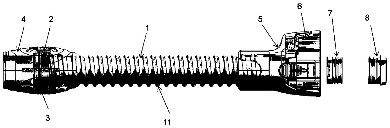
[0030] As a specific embodiment of the present invention, figure 1 Schematic illustration of a side view perspective effect showing a heated breathing circuit Figure 1 A kind of heating breathing circuit, those skilled in the art understands, the present invention figure 1 It only shows the important components and structures disclosed and described in the present invention, but there are also some other components that are not disclosed in the present invention figure 1 It is described in , because it is not the invention point of the present invention, so it is not marked or described in the figure, but this does not mean that the present invention does not have these components. Simultaneously, in order to better describe the present application, the present invention figure 1 ma...


PUM


Abstract

The invention provides a heating breathing pipeline which is used for assisting a humidifying instrument to heat humidifying gas, and further preventing formation of condensate water. The heating breathing pipeline at least comprises a heating pipeline (1), a temperature sensor assembly (2) and a temperature heating assembly (3), the heating pipeline (1) is connected with the temperature sensor assembly (2) and the temperature heating assembly (3) respectively; wherein the temperature sensor assembly (2) and the temperature heating assembly (3) are of an injection molding integrated structureand are connected with the heating pipeline (1), a spiral heating assembly (11) is arranged on the outer circumferential surface of the heating pipeline (1) in the length direction, and the temperature heating assembly (3) is electrically connected with the spiral heating assembly (11). The heating breathing pipeline is simple in structure, convenient to use, good in safety, capable of effectivelypreventing secondary infection and extremely high in commercial value.

Description

technical field [0001] The invention belongs to the field of respiratory therapy, and relates to a matching accessory for a humidifier or a ventilator. Background technique [0002] The humidifier or ventilator is an important component of the ventilator. It uses physical heating to provide the appropriate temperature and humidity for the dry air-oxygen mixture, and uses the respiratory humidifier to warm and dry the gas of the patient treated by the ventilator. Is humidification an important measure in the treatment process? If the respiratory humidifier fails, it will directly affect the treatment effect of the patient. If the failure is serious, it will cause harm to the patient. While the humidifier and the ventilator are in working condition, It needs to be used with some supporting parts. For example, in order to ensure the temperature of the air outlet, merchants often install a breathing circuit on the humidifier to control the temperature of the air outlet. However,...

Claims


Application Information

Patent Timeline
Patent Type & Authority Applications(China)
IPC IPC(8): A61M16/16A61M16/00
CPCA61M16/0003A61M16/16A61M2205/3368A61M2205/3653
Inventor 周成广高攀孙明仪任晶李爽郭艳鑫
Owner SHENYANG RMS MEDICAL TECH
Why Eureka
Try Eureka