Double-light-source composite laser machining equipment and method

A technology of laser processing and dual light sources, applied in laser welding equipment, metal processing equipment, welding equipment, etc., can solve the problems of low processing efficiency, inability to process special-shaped holes, and inability to open holes, etc., to achieve highly flexible intelligent processing and high convenience Operation, to achieve the effect of full automation

Pending Publication Date: 2020-04-17
XIAN MICROMACH TECH CO LTD
View PDF8 Cites 0 Cited by
  • Summary
  • Abstract
  • Description
  • Claims
  • Application Information

AI Technical Summary

Problems solved by technology

People try to process with long-pulse high-power laser, but there are various problems in the process of long-pulse high-power laser processing. Long-pulse high-power laser processing is easy to cause the coating to fall off, and cracks occur at the junction of the coating and the metal layer. Long-pulse high-power lasers cannot process special-shaped holes, and the processed parts have rough surfaces and residues left on the surface
Although ultra-fast laser rotary cutting and scanning processing alone can avoid the problems in the long pulse processing process, and can process various special-shaped holes, the processing efficiency is too low, and the coated large thin-walled parts such as flame tubes, etc. Generally, there are tens of thousands of holes, and the processing of so many groups of holes takes a long time; on the other hand, because the power of ultra-fast laser processing is not as high as that of long pulses, the holes cannot be opened quickly, and heat will accumulate during the long-term processing. A larger heat-affected zone appears on the opposite side of the part

Method used


Image

  • Double-light-source composite laser machining equipment and method

Examples


Embodiment Construction

[0033] The present invention will be further described in detail below in conjunction with the accompanying drawings, so that those skilled in the art can implement it with reference to the description.

[0034] It should be understood that terms such as "having", "comprising" and "including" as used herein do not entail the presence or addition of one or more other elements or combinations thereof.

[0035] The terms "first" and "second" in the description and claims of the embodiments of the present invention are used to distinguish different objects, rather than to describe a specific sequence of objects. For example, the first reflective mirror, the second reflective mirror, etc. are used to distinguish different reflective mirrors, rather than to describe a specific order of the reflective mirrors.

[0036] Embodiments of the present invention will be further described below in conjunction with the accompanying drawings.

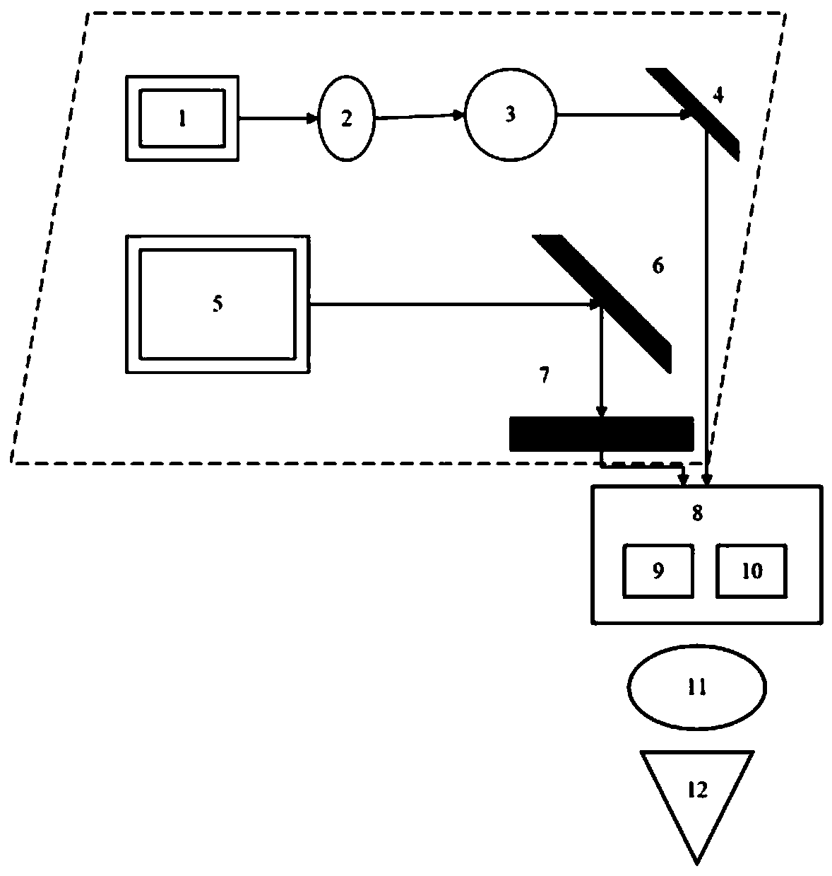
[0037] Such as figure 1 As shown, a dual light ...


PUM


Abstract

The invention discloses double-light-source composite laser machining equipment and method. The equipment comprises a long-pulse laser assembly, an ultrafast laser assembly, a machining assembly and acontrol system. The long-pulse laser assembly is used for carrying out rough machining on a workpiece to be machined. The ultrafast picosecond laser assembly is used for carrying out finish machiningon the workpiece obtained after rough machining. The machining assembly is used for implementing the machining process. The control system is used for controlling the long-pulse laser assembly, the ultrafast laser assembly and the machining assembly. According to the double-light-source composite laser machining equipment and method, the characteristics that in the long-pulse machining process, acoating is likely to fall off, and the hole morphology is poor are overcome, the quality of the hole morphology is guaranteed, the machining efficiency of ultrafast lasers is improved, and high-quality efficient machining of hole groups of a large thin-wall part with a coating is achieved.

Description

technical field [0001] The invention relates to the field of laser processing, in particular to a dual light source compound laser processing equipment and processing method. Background technique [0002] At present, laser processing technology has been applied to many industries such as machinery manufacturing, automobile industry, shipbuilding, aerospace, instrumentation and medical technology. Laser processing is to irradiate the laser beam to the surface of the processed object to generate light radiation heating to remove or melt the material and change the surface properties of the object to achieve the purpose of processing. Because laser processing does not require processing tools, has fast processing speed, small surface deformation, and high processing accuracy, it is widely used in drilling, cutting, welding, and heat treatment. Film hole cooling technology and thermal barrier coating are two effective means to improve the working environment of the flame tube. ...

Claims


Application Information

Patent Timeline
Patent Type & Authority Applications(China)
IPC IPC(8): B23K26/00B23K26/382B23K26/70
CPCB23K26/00B23K26/382B23K26/70B23K26/702
Inventor 贾北北朱文宇陈俊威乔文刚钱杰金春龙
Owner XIAN MICROMACH TECH CO LTD
Why Eureka
Try Eureka