
A high-speed machine laying weft winding method

A high-speed machine and weft laying technology, which is applied in textiles and papermaking, knitting, warp knitting, etc., can solve the problems of poor surface quality, low production efficiency, and slow weaving speed of composite fabrics, and reduce the incompleteness of yarn hanging The probability of occurrence, the effect of improving production efficiency and speeding up yarn laying speed

Active Publication Date: 2021-04-27
NEWTRY COMPOSITE
View PDF6 Cites 0 Cited by
  • Summary
  • Abstract
  • Description
  • Claims
  • Application Information

AI Technical Summary

Problems solved by technology

[0004] At present, the yarn winding method adopted in the prior art is to hang the yarn by raking needles up and down. The multi-axial high-speed machine adopting this winding method has the following two defects. First, the existing winding method is currently used. The spindle speed of the high-speed machine of the yarn method is 700r / min, the yarn laying is slow, the weaving speed is relatively slow, and the production efficiency is low; poor surface quality

Method used


Image

  • A high-speed machine laying weft winding method
  • A high-speed machine laying weft winding method
  • A high-speed machine laying weft winding method

Examples


Embodiment Construction

[0033] The present invention will be described in further detail below in conjunction with the accompanying drawings.

[0034] Wherein the same components are denoted by the same reference numerals. It should be noted that the words "front", "rear", "left", "right", "upper" and "lower" used in the following description refer to the directions in the drawings, and the words "bottom" and "top "Face", "inner" and "outer" refer to directions toward or away from, respectively, the geometric center of a particular component.

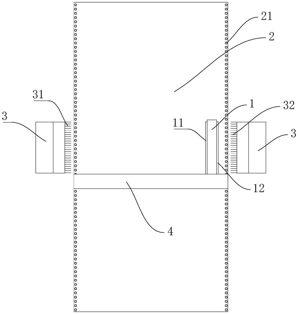
[0035] A high-speed machine laying weft winding method, such as figure 1 As shown, based on the following equipment: including weft yarn bed 2, trolley 1, weft laying rake 3, weft laying beam 4, servo motor unit and PLC controller;

[0036] The weft yarn bed 2 is a conveyor belt structure, installed on the frame, and the frame is placed on the ground, and the weft yarn bed 2 drives the fabric to move under the action of the first servo motor;

[0037] The t...


PUM


Abstract

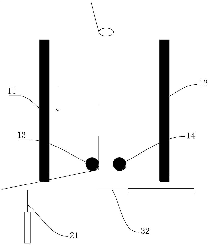
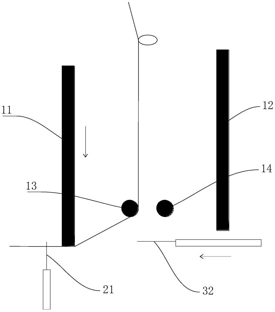
The invention discloses a high-speed machine laying weft winding method, belonging to the field of composite material production equipment, which can significantly increase the weaving speed, and the yarn is not easy to fall off from the weft needle. The steps are as follows: S1: the trolley moves right to the right side of the weft bed Stop and lay weft from right to left; S2: While the left yarn pressing plate is pressed down, the right rake needle moves forward for the first time, and during the first forward movement of the right rake needle, the right weft needle has already Hanging to the yarn; S3: While the left yarn pressing plate is lifted, the right rake needle moves forward for the second time, and the right rake needle seals the return thread opening; S4: The trolley moves along the length direction of the weft bed by one weft laying width ;S5: The trolley moves to the left along the weft laying direction, and it will cross the right weft needle, and the trolley continues to move to the left. When the right yarn pressing plate moves out of the right weft yarn needle, the right yarn pressing plate presses down to press the yarn into the right weft yarn At the same time, the raking needle on the right side moves back; S6: the trolley moves to the left and stops on the left side of the weft bed, and lays weft from left to right. The invention is suitable for the production of composite material fabrics.

Description

[0001] A high-speed machine laying weft winding method technical field [0002] The invention relates to a yarn winding method, in particular to a high-speed machine laying and weft winding method. Background technique [0003] Yarn winding means that the trolley lays the weft to one side of the weft needle bed, and winds the yarn around the outside of the weft needle. When the weft laying width is reached, the trolley lays weft to the other side of the weft needle bed, and winds the yarn again, so that the weft is reciprocated. [0004] At present, the yarn winding method adopted in the prior art is to hang the yarn by raking needles up and down. The multi-axial high-speed machine adopting this winding method has the following two defects. First, the existing winding method is currently used. The spindle speed of the high-speed machine of the yarn method is 700r / min, the yarn laying is slow, the weaving speed is relatively slow, and the production efficiency is low; Surfac...

Claims


Application Information

Patent Timeline
Patent Type & Authority Patents(China)
IPC IPC(8): D04B27/00
CPCD04B27/00
Inventor 谈源徐万里刘勇俊何小伟陈香伟
Owner NEWTRY COMPOSITE
Learn More