

Double-layer steel plate combined shear wall with transverse hole-forming corrugated web
A technology of steel plate shear wall and composite shear wall, which is applied in the direction of walls, building components, buildings, etc., can solve the problems of difficulty in transportation, improve the stable bearing capacity under shear, be easy to process and manufacture, and improve the bearing capacity under compression. Effect
- Summary
- Abstract
- Description
- Claims
- Application Information
AI Technical Summary
Problems solved by technology
Method used
Image

Examples
Embodiment Construction
[0022] Below in conjunction with accompanying drawing, the embodiment of this patent is described in detail.
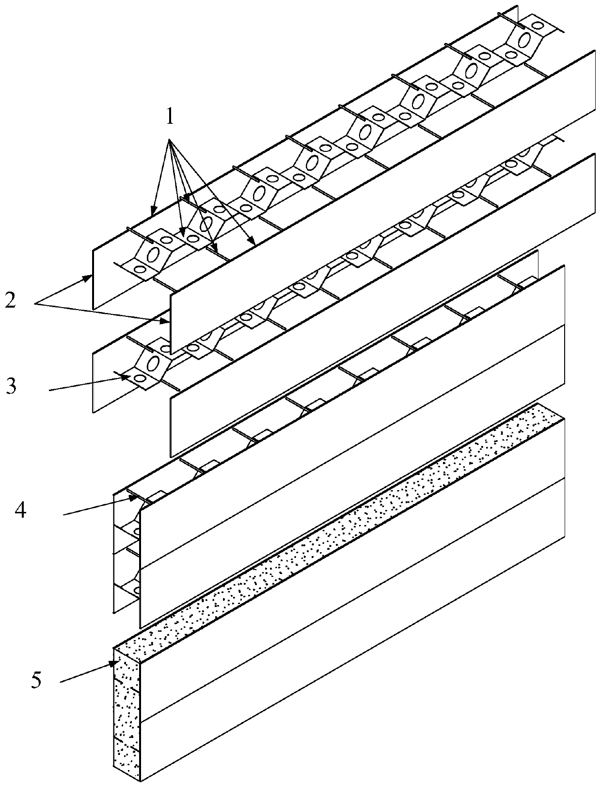
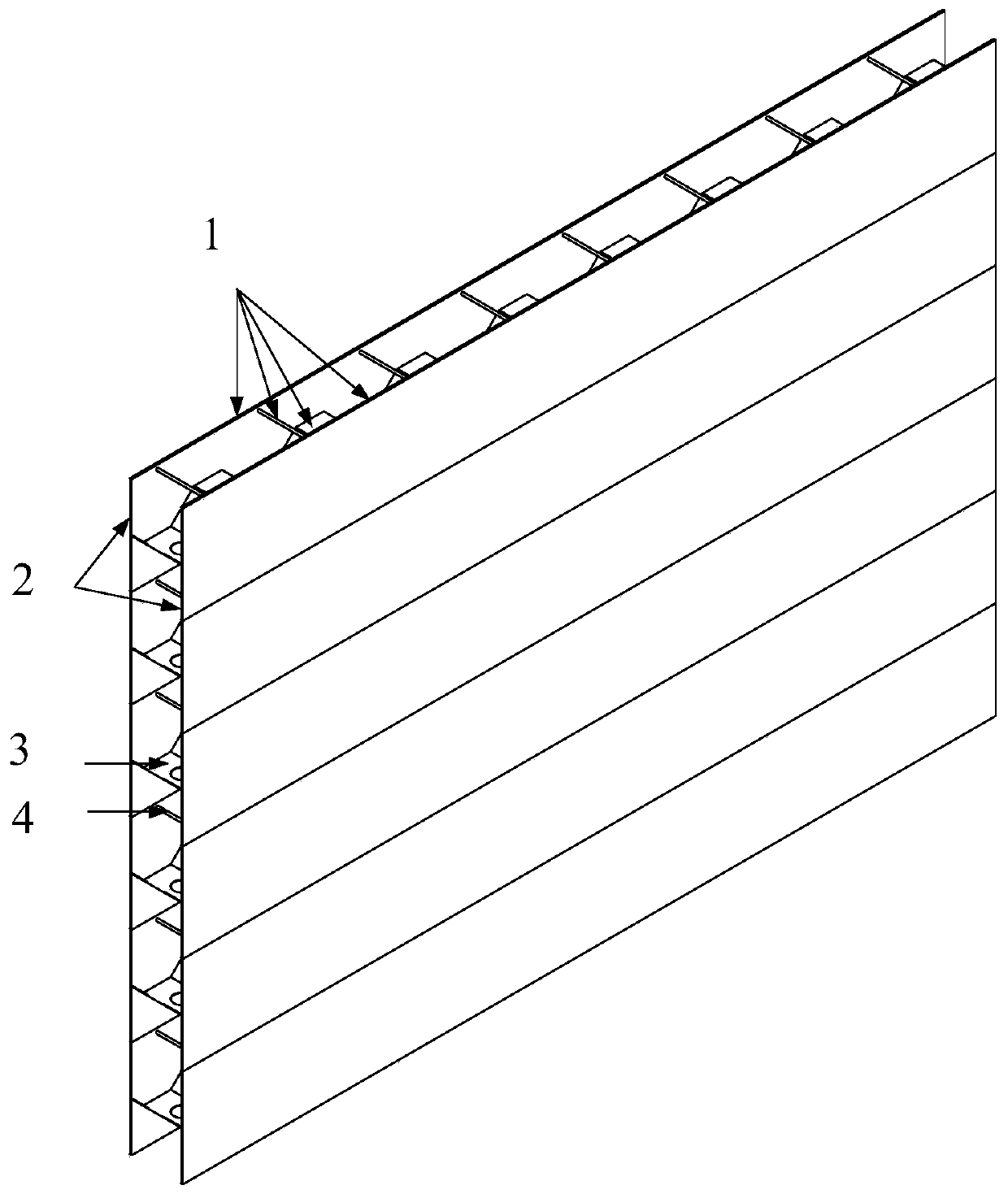
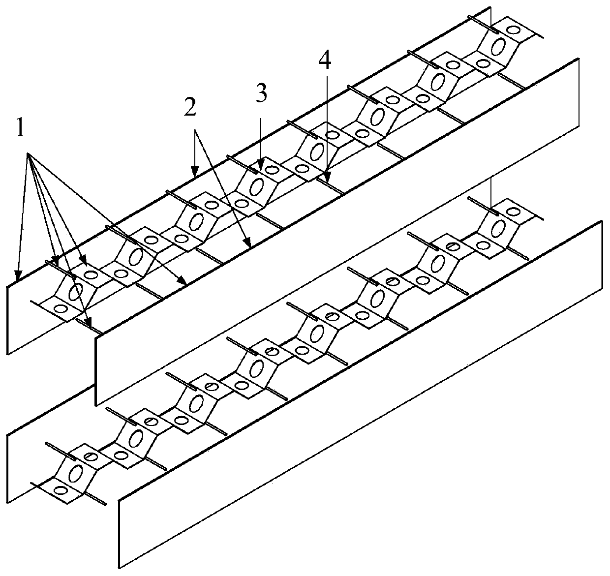
[0023] Such as Figure 1-6 As shown, a double-layer steel plate composite shear wall with a horizontal opening corrugated web includes the following components.
[0024] 1——steel plate shear wall unit;
[0025] 2 - Outer steel plate;
[0026] 3——Open corrugated web;
[0027] 4 - tie rod;
[0028] 5 - Concrete.
[0029] Such as Figure 1~4 As shown, the device consists of several steel plate shear wall units (1) welded to form a double-layer steel plate shear wall, and then concrete (5) is poured between the steel plates to form a double-layer steel plate combined shear wall with a horizontal opening and corrugated web. force wall; the steel plate shear wall unit (1) is composed of two outer steel plates (2), a corrugated web with holes (3) and a tie rod (4); the corrugated web with holes (3) is welded in the center Between the outer steel plates (2), tie rods (...
PUM
 Abstract
Description
Claims
Application Information