Operation-controllable roof-cutting pressure-relief gob-side entry retaining method

A technology of roof cutting pressure relief and empty entry retaining, which is applied in earth-moving drilling, discharging machinery, ground mining, etc. Cantilever length, stress concentration relief, small dynamic disturbance

Active Publication Date: 2020-04-17
CHINA UNIV OF MINING & TECH
View PDF6 Cites 17 Cited by
  • Summary
  • Abstract
  • Description
  • Claims
  • Application Information

AI Technical Summary

Problems solved by technology

[0003] The existing pressure relief methods are mainly roof cutting, including blasting and hydraulic fracturing. Although these two methods can reduce mine pressure to a certain extent, they also have defects that cannot be ignored. : The blasting method is poor in operability when drilling and cutting the top of the blasting hole, which can easily cause excessive blasting or insufficient blasting; the amount of blasting engineering and explosive consumption is large, the cost is high, and it causes underground air pollution; the blasting impact is easy to damage the bracket and requires secondary blasting. Strengthen support; not suitable for high gas mines
The top cutting speed of hydraulic fracturing is slow, the depth and range of hydraulic cutting are difficult to control, and the water must be kept under high pressure, which makes the operation difficult and is not conducive to the efficient production of coal mines

Method used


Image

  • Operation-controllable roof-cutting pressure-relief gob-side entry retaining method
  • Operation-controllable roof-cutting pressure-relief gob-side entry retaining method
  • Operation-controllable roof-cutting pressure-relief gob-side entry retaining method

Examples


Embodiment Construction

[0025] The present invention will be further described below in conjunction with accompanying drawing.

[0026] like Figure 1 to Figure 4 As shown, a controllable method of roof cutting, pressure relief and gob-side entry retention includes the following steps:

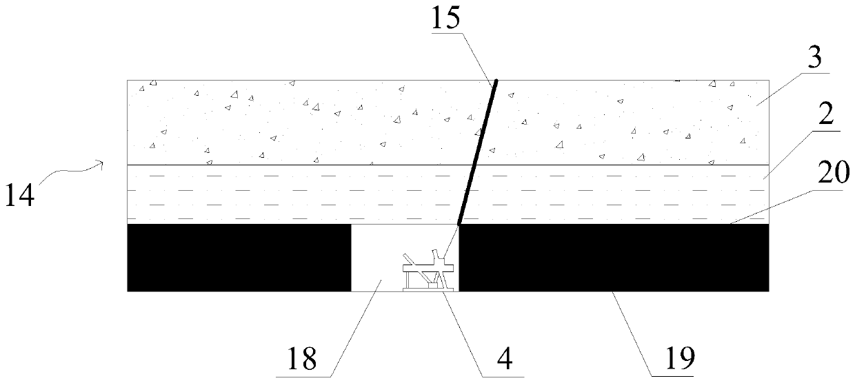
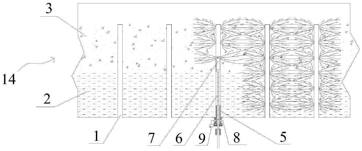
[0027] (1) Based on the original supporting foundation of the gob-side roadway 18, before the recovery of the mining face 19, the advanced working face is set up with a plurality of boreholes 1 at equal intervals in the rock formation 14 along the extension direction of the roadway 18, and the boreholes 1 start from The direct roof 2 extends obliquely to the interior of the basic roof 3 at its upper end;

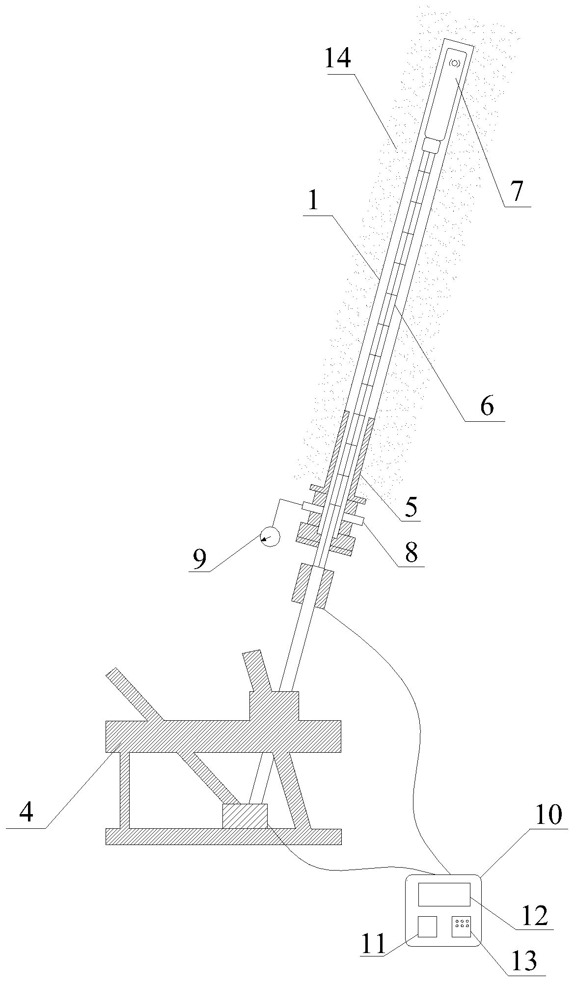
[0028] (2) Shock wave device 4 is installed below the first borehole 1. Shock wave device 4 includes hole sealer 5, push rod 6 and shock wave generator 7. Shock wave generator 7 is arranged on the upper end of push rod 6. Shock wave generator 7 and the outer diameter of the push rod 6 are smaller than the diamete...


PUM


Abstract

The invention provides an operation-controllable roof-cutting pressure-relief gob-side entry retaining method which comprises the steps that a plurality of drill holes are formed in an advance workingface in the extending direction of a roadway, and the drill holes obliquely extend into a basic roof; a shock wave device is installed below the drill holes, a shock wave generator is sent to the bottom of the drill holes, and a hole packer is in sealing fit with a hole opening; injecting water into the drill holes from a water injection port, and starting the shock wave generator after the drillholes are filled with water to enable shock waves to impact along the roadway extension direction; the shock wave generator is repeatedly loaded at the bottom of the drill holes to break the rock stratum to a certain range, and then the push rod is contracted to carry out the next-stage operation until the push rod is contracted to the hole opening to finish the first drilling operation; performing the next drilling operation until all the drilling operation is completed; the rock stratum is sheared and broken at a pre-splitting kerf formed by penetration of the drill holes; and after the working face is pushed, single supports are arranged for temporary supporting. The method is controllable in roof cutting, easy to operate and good in safety performance, operation can be completed quickly, and safe and efficient production of a coal mine is guaranteed.

Description

technical field [0001] The invention relates to an operation-controllable roof cutting and pressure relief method for gob-side entry retention, and belongs to the technical field of roof cutting and pressure relief in underground coal mines. Background technique [0002] my country's coal mining is mainly underground mining. With the advancement of the working face, the hard roof within the basic roof range on the side of the mining roadway will form a long-arm beam suspended roof. With the periodic pressure of the working face, the suspended roof will Tilting to the gob area, resulting in the increase of lateral concentrated stress, resulting in the destruction of the coal body at the edge of the coal pillar, the bending of the single pillar, and the breakage of the anchor rod and anchor cable, and then the concentrated stress is transferred to the deep part, eventually triggering a series of mine pressure disasters. The existence of strong mine pressure in the stope serious...

Claims


Application Information

Patent Timeline
Patent Type & Authority Applications(China)
IPC IPC(8): E21C41/18E21C37/12E21C37/00
CPCE21C37/00E21C37/12E21C41/18
Inventor 李桂臣毕瑞阳孙长伦许嘉徽梁巨理荣浩宇
Owner CHINA UNIV OF MINING & TECH
Why Eureka
Try Eureka