Cooling device for glass product

A cooling device and product technology, applied in household refrigeration devices, applications, household appliances, etc., can solve problems such as low cooling efficiency of cooling equipment, and achieve the effects of improving cooling efficiency, facilitating adjustment, and facilitating evaporative cooling

Active Publication Date: 2020-04-17
安徽超文玻璃科技有限公司
View PDF6 Cites 1 Cited by
  • Summary
  • Abstract
  • Description
  • Claims
  • Application Information

AI Technical Summary

Problems solved by technology

[0004] The technical problem to be solved by the present invention is to provide a cooling device for glass products to solve the problem of low cooling efficiency of existing glass product cooling equipment

Method used


Image

  • Cooling device for glass product
  • Cooling device for glass product
  • Cooling device for glass product

Examples


Embodiment 1

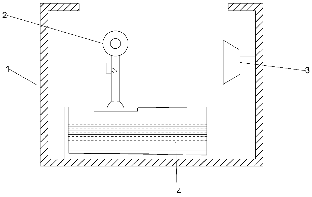
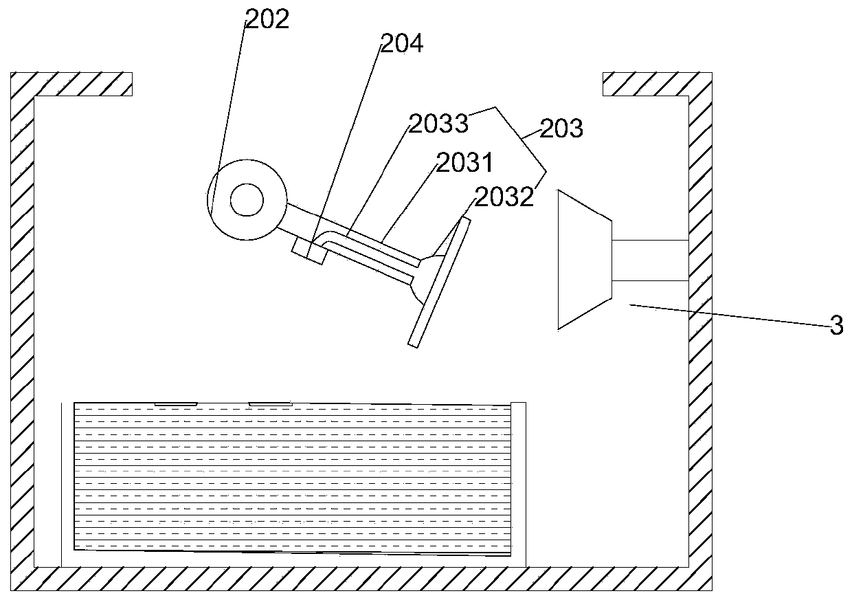
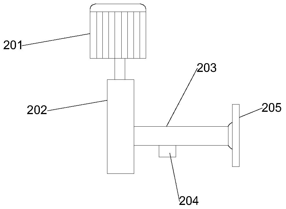
[0032] figure 1 It is a structural schematic diagram of a cooling device for a glass product in which the product to be cooled is at the lowest end in Example 1 of the present invention; figure 2 It is a structural schematic diagram of a cooling device for a glass product after the product to be cooled is rotated at a certain angle in Example 1 of the present invention; Figure 8 It is the overall three-dimensional schematic diagram of Embodiment 1 of the present invention; as figure 1 , figure 2 and Figure 8 , a cooling device for glass products, comprising a box body 1, a clamping mechanism 2, a drying mechanism 3, a cooling water tank 4 and a position adjustment mechanism 5, a cooling water tank 4 is placed at the bottom of the box body 1, and the cooling water tank 4. There is cooling water inside. The top of the cooling water tank 4 is provided with a clamping mechanism 2 fixedly connected to the inner side of the rear wall of the box body 1. The clamping mechanism ...

Embodiment 2

[0044] Figure 5 It is a structural schematic diagram of a cooling device for glass products in Example 2 of the present invention;

[0045] Figure 6 It is a three-dimensional schematic diagram of the position adjustment mechanism in Embodiment 2 of the present invention; Figure 7 It is a structural schematic diagram of a cooling device for a glass product after the position of the cooling device is adjusted in Example 2 of the present invention; Figure 5 , Figure 6 , Figure 7 The difference between embodiment 2 and embodiment 1 is that it also includes a position adjustment mechanism 5, which is fixedly connected to the side wall of the box body 1 by welding.

[0046] Such as Figure 5 and Figure 6 , the position adjustment mechanism 5 includes an arc-shaped plate 501, a connecting rod 502, a second magnet 503, a spring 504 and an arc-shaped slide rail 505, and the vertical section of the arc-shaped plate 501 is a fan-shaped mechanism whose center angle is greater...


PUM


Abstract

The invention relates to a cooling device for a glass product. The cooling device comprises a box body, a clamping mechanism, a drying mechanism, a cooling water tank and a position adjusting mechanism. The cooling water tank is placed at the bottom of the box body, the clamping mechanism fixedly connected with the inner side of the rear wall of the box body is arranged above the cooling water tank, the clamping mechanism is used for driving the product to be cooled to rotate while being connected with the product to be cooled, and the inner surface of the right side wall of the box body is fixedly connected with the drying mechanism. In the cooling device, a motor drives a rotating rod to rotate forwards and backwards, and the rotating rod drives a fixing mechanism to rotate along with the rotating rod, when a sucking disc is in contact with the product to be cooled, after an air suction pump is started, the air suction pump can suck air, at the moment, the air inside the sucking discis sucked out, and the external air pressure is larger than the air pressure inside the sucking disc, so that the product to be cooled can be well fixed; and when the fixing rod is vertically downward; the product to be cooled is submerged by cooling water in the cooling water tank, so that the cooling efficiency of the glass product is greatly improved.

Description

technical field [0001] The invention relates to the field of glass processing, in particular to a cooling device for glass products. Background technique [0002] With the continuous progress and development of society, glass products are becoming more and more important in life, whether it is housing or office space, glass products can be seen everywhere. In the production process of glass products, cooling is often required, but most of them are cooled by cooling fans or non-contact cooling liquid, so the cooling efficiency is not high; [0003] The utility model patent with the application number "CN201821661036.4" specifically discloses a cooling device for laminated glass production, including a frame, which is equipped with a transmission mechanism for transmitting laminated glass and a placement net at the discharge end of the transmission mechanism. The frame is equipped with cooling fans on the upper and lower sides of the placement net, and the air outlets of the ...

Claims


Application Information

Patent Timeline
Patent Type & Authority Applications(China)
IPC IPC(8): F25D1/02
CPCF25D1/02
Inventor 谭超文谭秀兵曹敏谈岫学
Owner 安徽超文玻璃科技有限公司
Why Eureka
Try Eureka